OmniTek XR User Guide, Software Release 2.3 Page 23
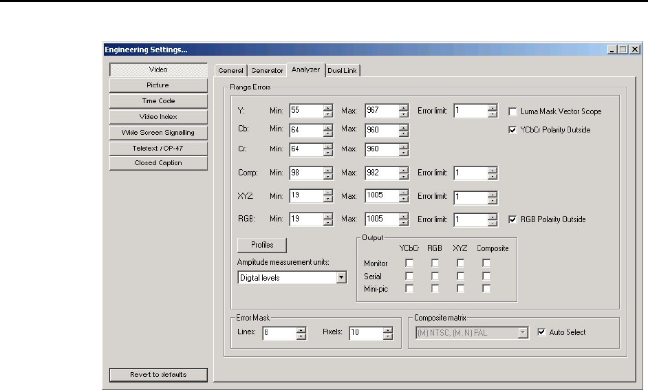
Video: Analyzer Settings
Range Errors
OmniTek XR can detect and count where the incoming video falls outside pre-defined
luma/chroma ranges. The levels that trigger an error are determined in this dialogue.
You specify the minimum and maximum IN RANGE values for each luma / chroma
component. Normally, the YCbCr Polarity Outside box is ticked and values less than the
minimum or greater than the maximum will be detected and reported. If however the
YCbCr Polarity Outside box is cleared, values within the specified ranges, rather than
outside the ranges, will be reported. The Error limit setting defines a further threshold for
reporting an error, based on the percentage of the frame for which the values are in error.
Many companies set the minimum value for both luma and chroma to 0%, which equates
to 64 as a digital video level. The maximum values would normally be set to 100%, which
equates to a digital video level of 940 for luma, and 960 for the two chroma components.
OmniTek XR similarly detects and counts RGB and XYZ range errors (where supported).
These are calculated by converting the data into RGB / XYZ colour space, and then
noting if any pixels are outside the specified RGB / XYZ colour cube. Many companies
set the minimum acceptable RGB value to be -5%, and the maximum to be +105%.
These provide the default values used in this dialogue.
OmniTek XR also counts the number of pixels for which the composite signal determined
from the incoming video falls outside the maximum and minimum values specified in this
dialogue for this composite signal.
The number of frames for which the signal lies outside the specified ranges is reported on
in the Video Status window (see page 84) and logged in the Event Log window (see
page 104).
Amplitude Measurement Units
Use this drop-down menu to select the units in which the above ranges are expressed.
Output
For each of the above errors, any erroneous pixels can be keyed out and replaced with a
flashing black and white signal. The Output section of this dialogue allows you to select
where the flashing pattern will be displayed. Each error condition can be independently
routed to the monitor output, or to the serial digital output, or for display on the Mini-Pic
on the VGA monitor.


