


Introduction
1-33910-A2-GN32-30 November 1996
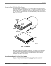
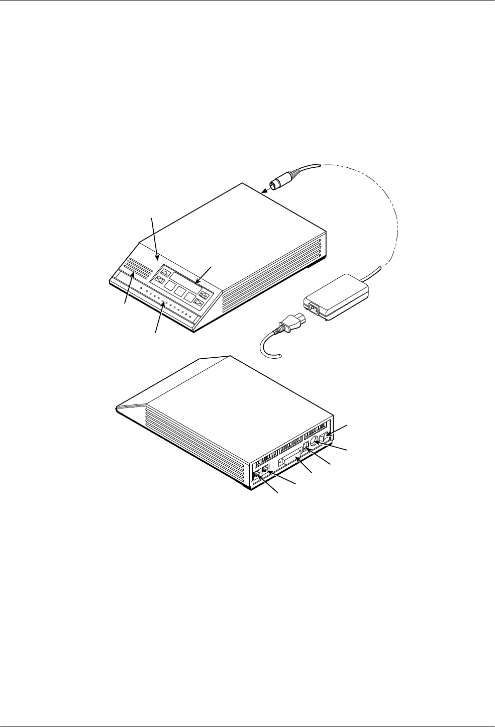
Standalone Model 3910 4-Wire/2-Wire Modem
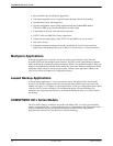
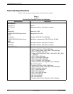
The standalone Model 3910 modem (Figure 1-1) is capable of either 4-wire/2-wire leased-line or
dial operation. The modem is controlled using either AT commands or the diagnostic control panel
(DCP). The DCP consists of a liquid crystal display (LCD), three function keys, four directional
keys, and a row of 13 LED status indicators. For a better understanding of DCP operation, refer to
Chapter 3,
DCP Operation
.
SPEAKER
DIAGNOSTIC
CONTROL
PANEL
LCD AND
KEYPAD
STATUS
INDICATORS
POWER
SUPPLY
POWER
CORD
496-14160-0
3
POWER
ON/OFF
LEASED
DIAL
DTE 1
NMS
POWER IN
Figure 1-1. Model 3910
The rear of the modem contains an ON/OFF power switch, a low voltage dc power connector
, an
8-pin modular connector (LEASED) for leased-line connection, an 8-pin modular connector
(DIAL) for dial-line or leased-line backup, a 4-pin modular connector (NMS) for network
management, and a DB-25-S DTE connector.
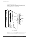
Carrier-Mounted Model 3911 4-Wire/2-Wire Modem
The carrier-mounted Model 3911 modem (Figure 1-2) is capable of either 4-wire/2-wire
leased-line or dial operation and installs into a COMSPHERE 3000 Series Carrier. The