


COMSPHERE 3900 Series Modems
2-2 November 1996 3910-A2-GN32-30
For the carrier-mounted model
• Installation instructions
•
Model 391
1 modem
• Rear connector plate with two DB-25-S edge card connectors
If any hardware components are damaged, notify your service representative. Return equipment
using the procedures described in the
Government Requir
ements and Equipment Return section of
Chapter 1.
Customer-Supplied Equipment
The following customer
-supplied equipment is required to complete a data communications system
using the Model 3910 modem:
• A DTE with an available EIA-232-D serial port.
• A standard EIA-232-D cable with a DB-25-P (plug) connector at one end to attach to the
modem.
• One of the following modular leased or dial network interfaces:
—
JM8 for leased-line applications.
— RJ1
1C for dial permissive applications.
The following customer-supplied equipment is required for the installation of a Model 3911
modem:
• A COMSPHERE 3000 Series Carrier.
• A 50-pin mass termination cable.
• One of the following modular or 50-pin leased or dial network interfaces:
— RJ1
1C for single line dial permissive applications.
—
RJ21X for multiple line dial permissive applications.
— 66 punchdown block.
• One Network Interface Module (NIM) for modems installed in Slots 1–8 and one NIM for
modems installed in Slots 9–16 (required for dial-line applications).
For installation of the COMSPHERE 3000 Series Carrier into a cabinet, refer to the COMSPHERE
3000 Series Carrier
, Installation Manual.
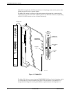
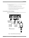
Model 3910 Modem Installation
Before
installing your standalone modem, make sure your installation site is clean and
well-ventilated. Allow space around the modem for installing cables and telephone cords, and
make sure the modem is located within reach of the ac power outlet. The distance between your
modem and DTE should be minimized if DTE data rates exceed 19,200 bps. Also, low capacitance
cables may be necessary for speeds greater than 19,200 bps or distances greater than 50 feet.