


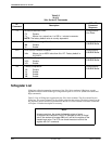

AT Command Set and S-Registers
5-133910-A2-GN32-30 November 1996
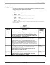
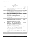
Table 5-3
(7 of 8)
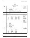
391x Series AT Commands
AT
Command
DCP LCD
Command
Sequence
Description
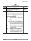
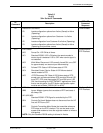
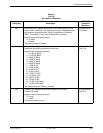
\D
n
CTS Control.
\D0 Forced On. Forces CTS to always ON.
\D1 Standard RS232.
\D2 Wink When Disconnect. CTS is turned OFF for 1 to 2 seconds
upon a disconnect.
\D3 Follows DTR. The state of CTS follows the state of DTR.
\D4 Follows RTS. The state of CTS follows the state of RTS.
Configure\Edit\
DTE Interface
\G
n
Modem to Modem Flow Control.
\G0 Disable.
\G1 Enable.
Configure\Edit\
V42/MNP/Buffer
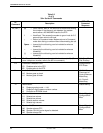
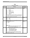
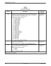
\K
n
Buffer Control, Send Break Control, Break Forces Escape.
Break Buffer
Send Break
Break Forces
Control: Control: Escape:
\K0 Discard Data Break First Enable
\K1 Discard Data Break First Disable
\K2
Keep Data
Break First Enable
\K3
Keep Data
Break First Disable
\K4
Keep Data
Data First
Enable
\K5
Keep Data
Data First
Disable
Break
Buf
fer
Control:
Configure\Edit\
V42/MNP/
Send Break
Control:
Configure\Edit\
V42/MNP/Buffer
Break Forces
Escape:
Configure\Edit\
DTE Dialer
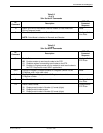
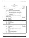
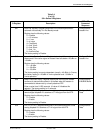
\N
n
Error Control Mode.
\N0 Buffer Mode.
\N1 Direct Mode.
\N2 MNP or Disconnect.
\N3 MNP or Buffer.
\N4 V.42/MNP or Disconnect.
\N5 V.42/MNP or Buffer.
\N6 LAPM_or_Disc
\N7 LAPM_or_Bufr
Configure\Edit\
V42/MNP/Buffer
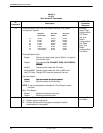
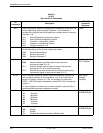
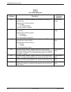
\Q
n
Flow Control of DTE, Flow Control of Modem.
Flow Control Flow Control
of DTE:
of Modem:
\Q0 Disable Disable
\Q1 XON/XOFF XON/XOFF
\Q2 CTS to DTE Disable
\Q3 CTS to DTE R
TS to Mdm
\Q4 XON/XOFF Disable
\Q5 Disable XON/XOFF
\Q6 Disable R
TS to Mdm
Configure\Edit\
V42/MNP/Buffer