


Pin Assignments
C-33910-A2-GN32-30 November 1996
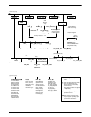
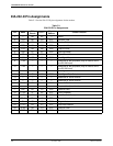
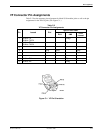
VF Connector Pin Assignments
T
able C-2
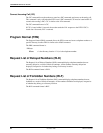
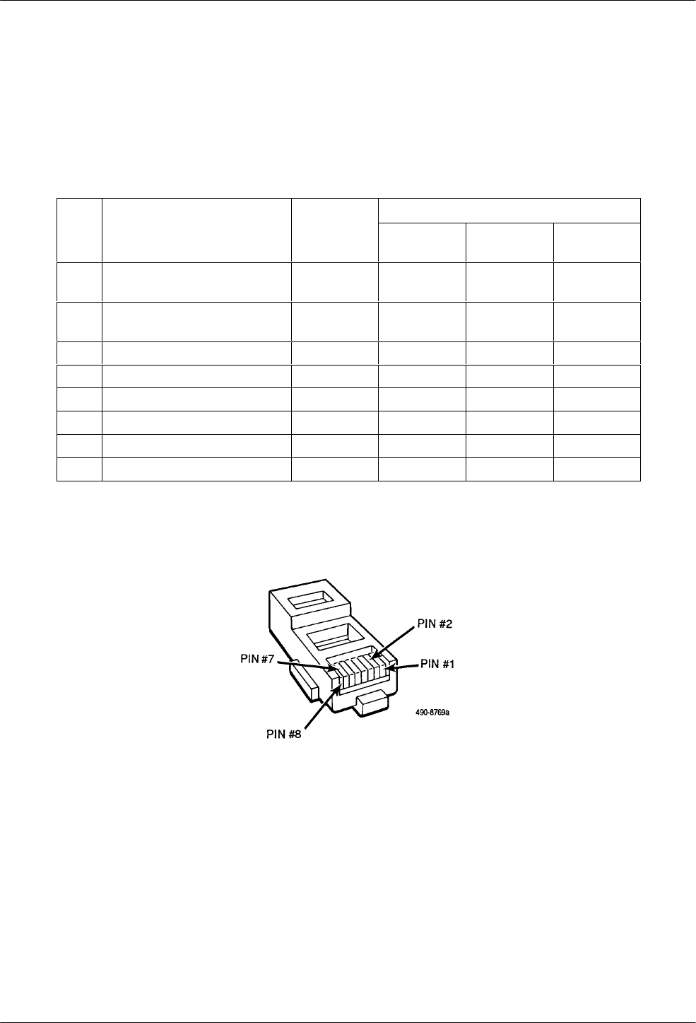
lists the connector pin assignments for Model 3910 modular jacks as well as the pin
assignments for the TELCO jacks. (See Figure C-1.)
Table C-2
VF Connector Pin Assignments
Type of Telco Jack
Pin Leased Dial
RJ11 JM8
6-Pin
Leased
1 4-Wire: TX
2-Wire: TX/RX
Ring 1
2 4-Wire: TX
2-Wire: TX/RX
Tip 1
3
4 Ring Ring Ring
5 Tip Tip Tip
6
7 4-Wire: RX Tip
8 4-Wire: RX Ring
Figure C-1. VF Pin Orientation