


Modem Installation
2-33910-A2-GN32-30 November 1996
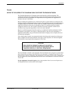
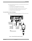
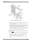
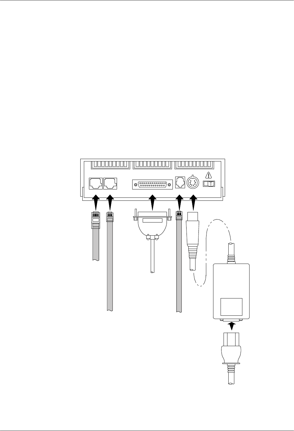
The rear panel of the Model 3910 modem (Figure 2-1) has the following switches and connectors:
• An ON/OFF power switch.
• An 8-pin DIN type power receptacle (PWR) for the dc power supply.
• An 8-pin modular keyed jack (LEASED) for 4-wire/2-wire leased lines.
• An 8-pin modular keyed jack (DIAL) for backup lines (2-wire dial or 2-wire leased).
• A 4-pin modular jack for the (NMS) network management system connection.
• A 25-pin DB-25-S receptacle for the DTE interface.
Connecting Cables to the Model 3910 Modems
Figure 2-1
shows how Model 3910 modems are connected to certain TELCO jack types using the
appropriate cables. For pin assignments, refer to Appendix C.
8-POSITION,
8-CONDUCTOR
PLUG FOR
LEASED-LINE
NETWORK
OPERATION
6-POSITION,
4-CONDUCTOR
PLUG FOR
PERMISSIVE
DIAL NETWORK
OPERATION
DB-25-P
CONNECTOR
FOR DATA
TERMINAL
EQUIPMENT
OPERATION
SUB-MINIATURE,
4-CONDUCTOR
PLUG FOR
NETWORK
MANAGEMENT
OPERATION
POWER
SUPPLY
DTE
2
DTE 3 DTE 4
DTE 1LEASED DIAL NMS PWR ON OFF
NOTE:
THE DIAL JACK IS ALSO USED
FOR 2-WIRE LEASED BACKUP.
Figure 2-1. Model 3910 Rear Panel and Power Supply