


12 Pelco Manual C690M-E (11/04)
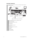
REAR PANEL CONNECTORS
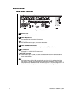
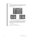
The components on the rear panel are shown in Figure 2. Making connections is explained in
the installation procedures.
COM 1
COM 2
1 2 3 4 5 6 7 8 9 10 11 12 13 14 15 16
HZ
75
HZ
75
SCS
NC
T
N
NNPR
SOAE
LS
1234
ON
OFF
DEFAULT IP RESET
ALARMS
5678 9101112 13 14 15 16
REL 1
NCN
OC
NCN
OC
REL 2
MON
OUT
TCP/IP
10/100
D
A
T
A
P
O
R
T
S
1
2
3
4
100-240~
50/60HZ
200 WATTS MAX
N.O.
N.C.
SUPERVISED
NOTE: SEE
SECTION.
CONNECTING
ALARMS
NOTE: SEE
IN THIS
SECTION.
RESET
BUTTONS
RESERVED
FOR FUTURE
USE
EXTERNAL MODEM
DX700EM
NTSC/PAL
MONITOR
NOTE: SEE THIS SECTION.DIPSWITCHES
LOOPING BNC
TERMINATION
SWITCH
ETHERNET
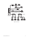
NOTE: SEE FIGURE 3 FOR DATACONNECTIONS.
8
2
1
5
10
11
3
9
6
7
4
8
12
Figure 2. Rear Panel Connections, DX2016 Models
1 Input and output BNC connectors (8 or 16 depending on model)
2 Video termination switches
3 Alarm inputs (8 or 16 depending on model)
4 Two relay connectors
5 Four DIP switches
6 Two RS-232 communication ports
7 One Ethernet port
8 One BNC for connecting an analog monitor
9 Two reset buttons
10 Power switch
11 Power cord receptacle
12 Four data interface ports