


Pelco Manual C690M-E (11/04) 21
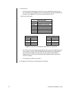
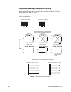
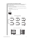
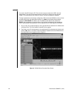
Supervised Alarm Input Configuration and Wiring
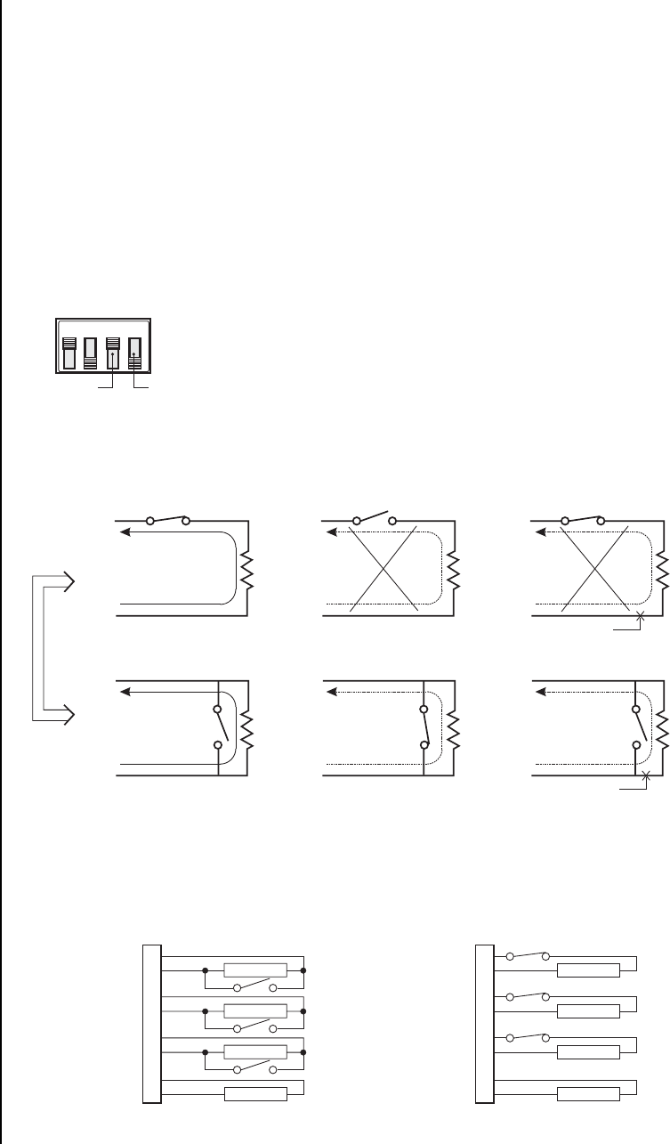
Supervised mode activates an alarm if the current in a line falls outside a specified range. This
blocks an attempt to defeat the alarm system by cutting a wire or through bypassing or
shorting a section of the circuit.
If the whole system is in supervised mode, then all inputs (including unused inputs) must be
terminated with 10K resistors (not included).
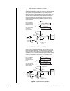
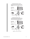
• If you want the alarm contacts to be N.O., then wire the terminating resistor in parallel with
the alarm contacts.
• If you want N.C., then wire the resistor in series.
Refer to Figure 7.
Figure 7. Supervised Alarm Input Wiring
1234
SWITCH SETTINGS
SUPERVISED (NTSC)
NTSC/PAL NOT USED
10K
ALM
UNIT
+V
GND
NO ALARM
NORMALLY CLOSED
10K
ALM
UNIT
+V
GND
NORMAL
ALARM CONDITION
10K
ALM
UNIT
+V
GND
ALARM CONDITION
CUT WIRE
10K
ALM
UNIT
+V
GND
NO ALARM
NORMALLY OPEN
10K
ALM
UNIT
+V
GND
NORMAL
ALARM CONDITION
10K
ALM
UNIT
+V
GND
ALARM CONDITION
CUT WIRE
SUPERVISED, NORMALLY OPEN
10K
10K
10K
10K
10K
10K
10K
10K
SUPERVISED, NORMALLY CLOSED
1
2
3
4
5
6
7
8
1
2
3
4
5
6
7
8
SUPERVISED, GROUP ALARM WIRING CONDITIONS
SUPERVISED MODE CONSIDERATIONS
INDIVIDUAL ALARM WIRING CONDITIONS