


Pelco Manual C690M-E (11/04) 15
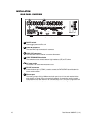
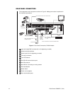
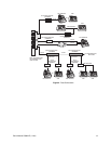
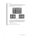
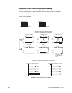
2. Connect the cameras. Plug standard coaxial cables (not supplied) from the cameras into
the top row of BNCs on the rear of the DVR. Camera 1 is the top left BNC. Set rear panel
DIP switch 3 to the correct position (UP=NTSC, DOWN=PAL). Set the video termination
switches to the proper setting: 75 ohms if no equipment is connected to the BNC looping
connector; HZ if equipment is connected to the BNC looping connector.
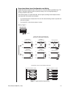
3. Connect a video monitor (if desired). The monitor will show a live camera view and will
follow the view selected on the controlling PC. Plug a standard coaxial cable (not sup-
plied) from a monitor into the MON OUT BNC on the DVR. Properly terminate (75 ohms)
at the monitor.
4. Set DIP switch 3 for NTSC/PAL operation. Set the alarm DIP switches (if desired) accord-
ing to the information in the
Connecting Alarms
section.
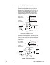
5. Connect alarms (if desired). Wiring gauge is not critical, but the maximum resistance
between alarm input and contact closure should be less than 150 ohms. Refer to the
Connecting Alarms
section for detailed information.
6. Connect relays (if desired). Connect mechanisms you want to control remotely, such as a
gate or door, to relays 1 and 2 (REL 1, REL 2). Use the C (common) post and either NO
(normally open) or NC (normally closed) depending on how you want the relay to operate.
An external fuse is required to protect against currents above 1 amp.
7. Connect POS terminals and/or ATMs (if desired). Refer to the
Connecting POS Terminals
and ATMs
section for details.
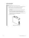
8. Connect power. Plug one end of the appropriate supplied power cable (USA or European
standard) into the receptacle on the rear of the DVR and the other end into a power outlet.