C1534M (1/06) 59
Print a Full-Size Single Image
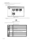
1. Open an image in the Capture Viewer.
2. From the Frame Capture Viewer menu, select File > Print. The image is printed with the filename and date stamp as displayed in the viewer
window.
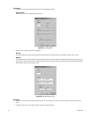
ALTERNATE Step 2
Select File > Print Setup to modify the printer settings, and then click Print.
NOTE: To use the print function, you must have a printer connected to the VMX210 workstation parallel port. Refer to the Windows 2000
documentation for printer installation instructions.
OPERATE AUXILIARIES AND OUTPUT POINTS
Operate Camera Auxiliaries
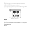
Camera auxiliaries defined through the camera device configuration procedures may be controlled from VMX200 through the following steps:
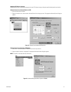
1. Drag the desired camera into one of the VMX200 video windows.
2. Right-click the VMX200 video window, and then select the appropriate auxiliary from the pop-up menu. The device is turned on.
If you display the pop-up menu again, you will see that the selected auxiliary control now has a check mark next to it. Once an auxiliary is
on, it will remain on until it is turned off or the system is shut down.
3. To turn the auxiliary off, display the pop-up menu and select the auxiliary. The check mark disappears.
Digital Output Point Controls
You can use VMX200 to control external relay devices such as lights, gates, or motors using the system’s digital output controls. Refer to
Configure Input/Output Points in the Additional Configuration section for instructions on configuring relay output points.
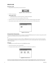
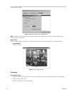
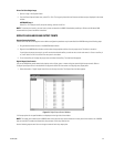
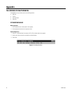
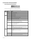
1. Select Automation > Digital Output Control from the site map menu bar. The Output Control window appears.
Figure 73. Digital Output Control Window
2. All output points for the specified device are displayed on the right side of the window.
NOTE: The output point number used in VMX200 refers to the physical relay contact number on the rear panel of the interface unit. VMX200
does not use the GPI numbers associated with relay contacts on the relay interface unit.
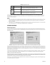
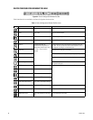
Use the following output control icons to change the state of each relay output point:


