60 C1534M (1/06)
Table G. Output Control Icons
Logic state example: A floodlight is normally off. The output point is configured to represent off as a “false” state. When you click the “true”
icon, the floodlight is turned on. Refer to Configure Input/Output Points in the Additional Configuration section for additional information on
output point startup configuration.
NOTES:
• Relay contact settings (such as normally open/normally closed) are configured through the DIP switches on the relay interface unit. These
settings are duplicated in the VMX200 configuration when you add the device (refer to the Reference Information for Adding Devices
section in the Appendix).
• The definition of “True” in VMX200 depends on the DIP switch setting. For example, if you configure relay contacts 1-16 in a relay interface
unit as normally open, then “True” equals open for VMX200 relay point 1 through point 16.
ADVANCED CONTROLS
Advanced Camera Controls
To access the advanced controls for a camera, right-click the camera icon on the site map image, and then select Advanced Controls from the
pop-up menu. Or you can right-click the mouse in the VMX200 video window displaying the desired camera, and then select Advanced Controls
from the pop-up menu.
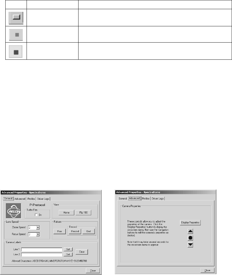
Figure 74. Sample Camera Advanced Properties Dialog Boxes: General Tab (left) and Advanced Tab (right)
The Advanced Properties dialog box provides a way to configure a camera’s special features. The specific fields contained in the dialog box vary,
depending on the features supported by the camera. For example, with a Spectra camera, you can configure settings such as camera labels, lens
speed, and patterns. The Display Properties button on the Advanced page opens the camera menu. The circle button below the Display Properties
button controls iris open and iris close.
In some cases, the Advanced Properties dialog box contains a Profile tab. Use this page to save camera settings as a specific “Profile” for that
camera. Profiles are loaded manually or through an automated macro. This is a useful feature for outdoor cameras that must adjust their
exposure for varying light conditions during the day.
Click the Driver Logs tab to view error messages related to the device driver. If system cameras are controlled by Coaxitron
®
through a switcher,
the driver log displays errors related to the switcher driver, since commands to move cameras are sent to the switcher. If system cameras are not
controlled through a switcher, the camera driver log displays camera errors and timeouts.
The driver log is a good troubleshooting tool, especially when used in combination with the Diagnostic Log. Refer to View the Diagnostic Log in
the Troubleshooting section of the Appendix.
Icon Icon Name Function
Momentary True/False Click this icon to momentarily change the output point’s state to “true.” When
you release the icon, the output point’s state returns to “false.”
True Click this icon to set the selected point to “true.” This icon appears pressed
down when the output point is in a “true” logic state.
False Click this icon to set the selected point to “false.” This icon appears pressed
down when the output point is in a “false” logic state.
