


SOLA 4000 - PCB Description
JUE 401268
100
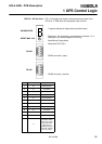
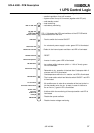
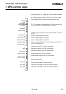
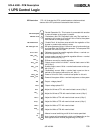
IPR front view FIG. 1.6 illustrates the LEDs, potentiometers, switches and test
sleeves of the IPR pcb that are accessible from the front.
- Parallel Operation On: This inverter is connected with another
or more inverters to the output in parallel.
- Redundancy Not OK: Redundant units only.The load has in-
creased or an inverter is off so that if this unit fails, the system
must transfer to the bypass supply.
- Parallel Fault: A fault has occurred with the regulation of the
inverter in parallel with another inverter.
- SSI pulse generator failure: A failure or loss of synchronism has
occurred within the SSI ON pulse generator. To reset press PB3
and then PB1 on the ICP pcb.
- Reference current for parallel regulation 6Vrms = nominal cur-
rent of the system (0.8 p.f.).
- Inverter output current for parallel regulation 6Vrms = nominal
current of this unit (0.8 p.f.).
- Difference current for parallel regulation
- Output current of this unit. 8Vdc = nominal load current of this
unit (0,8 p.f.)
- System output current. 8Vdc = nominal load current on the sys-
tem (0.8 p.f.)
- Redundancy current. 8Vdc = nominal load current on the re-
mainder of the system (without this unit, 0.8 p.f.)
- Power of this unit. 6Vdc = nominal load power on this unit
- Power of the system. 6Vdc = nominal load power on the system
- Output voltage phase T
- Output voltage phase R-S
- Adjust for 6Vrms at TP1 with nominal load current (0.8 p.f.)
- Adjust for 6Vrms at TP2 with nominal load current (0.8 p.f.)
- Adjust for 8Vdc at TP4 with nominal load current (0.8 p.f.)
- Adjust for 8Vdc at TP5 with nominal load current (0.8 p.f.)
- Adjust for 6Vdc at TP7 with nominal load
- Adjust for 6Vdc at TP8 with nominal load
- Manual: manual switching on/off of the inverter permitted
- Auto: inverter will automatically switch on/off depending on the
load applied and the internal programming of IPR pcb.
LD1 Parall.Operat
LD2 Red not ok
LD3 Parallel Fault
LD4 Pulse gen. Fail
TP2 I
out
=6V
rms
TP3 I
error
TP4 I
load
= 8V
TP5 I
syst
= 8V
TP6 I
red
TP1 I
ref
= 6V
rms
TP7 P
out
=6V
TP8 P
syst
= 6V
P1 I
ref
P2 I
out
P3 I
load
P4 I
syst
P5 P
out
P6 P
syst
Auto
S1
Manual
TP9
TP10
1 UPS Control Logic