


SOLA 4000 - Installation and Initial Start-Up
JUE 401265
25
1.3 Installation of additional optional cabi-
nets
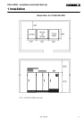
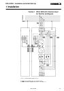
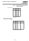
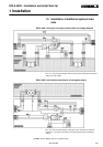
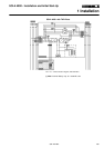
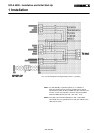
SOLA 4000 with input and output transformers for voltage adaption
FIG. 1.3.1 UPS connection diagram, with input and output transformers to adapt the
UPS to the on-site voltage.
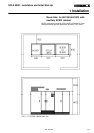
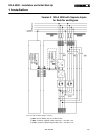
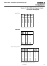
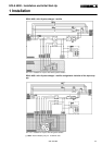
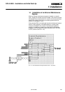
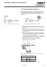
SOLA 4000 with isolation transformer of the bypass supply
FIG. 1.3.2 UPS connection diagram, with bypass input transformer to isolate the
neutral line (** 4-N may be connected to the supply neutral or earth or left discon-
nected.)
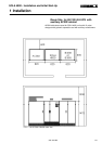
(*) Note: Internal Battery only for 10-30kVA units
1 Installation