


SOLA 4000 - PCB Description
JUE 401268
93
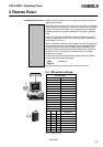
1 UPS Control Logic
1 UPS CONTROL LOGIC
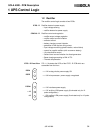
1.0 UPS Control Logic
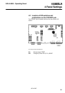
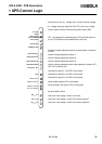
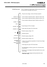
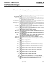
The UPS Control logic is situated in the centre of the front part of
the UPS. It consists of one rack with 7-8 PCBs (depending on the
system configuration). On the covers of the rack, the various
potentiometers, test points and LEDs are briefly labelled.
A more detailed explanation is given in this chapter.
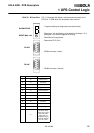
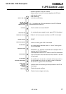
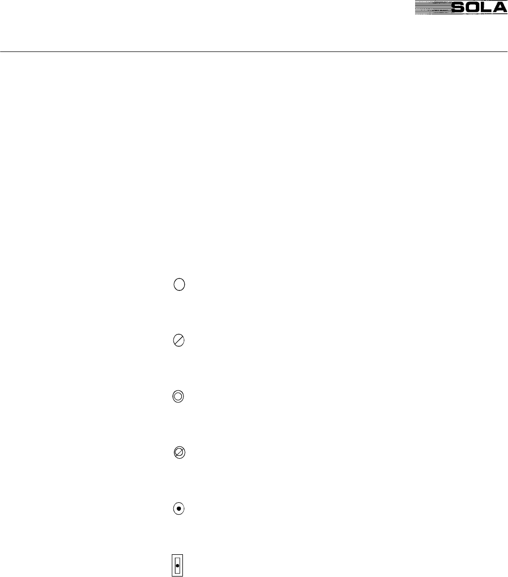
1.1 Legend of symbols used
LED (light emitting diode) - GREEN: normal condition
- RED: alarm condition.
- YELLOW: warning
Potentiometer - For adjustment
(only for qualified personnel)
Test Point - Requires a pin 2mm for
measurement.
Test point/switch - Insertion of a 2mm Pin disables
the described function
Pushbutton - Performs a reset or switching
operation
Micro switch - Switch from manual to auto
matic mode