


SOLA 4000 - PCB Description
JUE 401268
103
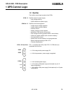
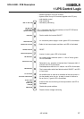
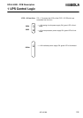
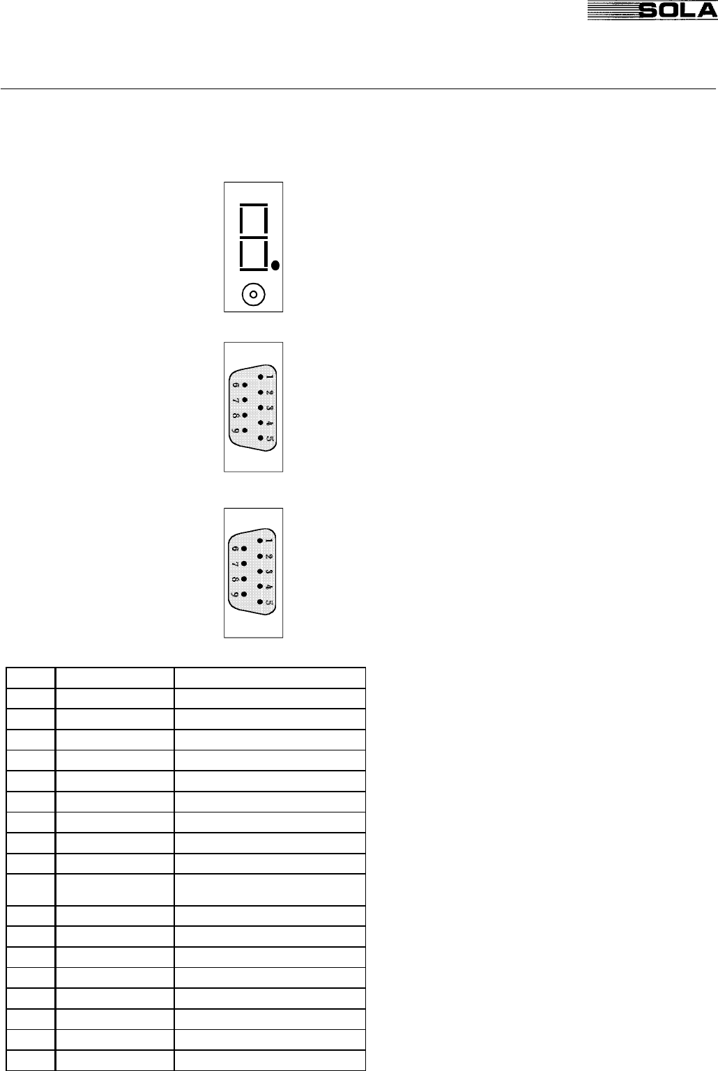
CPHC16 - S Front View
FIG. 1.8 illustrates the display, switches and connectors of the
CPHC16 - S PCB which are accessible from the front.
• 7 segment display for diagnostics (see table below)
• Manual transfer to bypass pushbutton
• RS232 connector (male)
• RS485 connector (female)
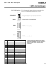
In normal condition the display shows a red seg-
ment rotating clockwise.If more than one alarm is
present, only the one with the higher priority
is displayed.
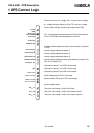
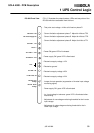
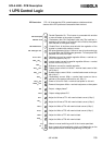
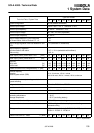
1 UPS Control Logic
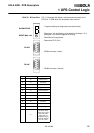
DIAGNOSTICS
Bypass
RS 232
RS 485
Priority Indication Diagnostics
1 8 E²PROM failure
2 F Bypass Fuses Blown or IRE open
3 C Phase failure
4 P Incorrect phase rotation
5
ll
Bypass square wave generation error
6 O Output out of tolerance
7 L Overload
8 4 Mains frequency out of tolerance
9 H Mains voltage out of tolerance
10 6
Auxiliary power supply failure on the
SS/FY pcb
11 b Bypass blocked
12 S Bypass not synchronised
13 d SSB failure
14 E Bypass system not available
15 9 Missing or false bypass trip signal
16 7 EPO activated
17 U IUG open
18 -- SSB on