


Chapters
1 INSTALLATION 3
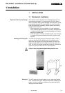
1.1 Mechanical Installation 3
1.2 Electrical Installation 8
1.3 Install. of Additional Optional Cabinets 13
1.4 Installation of an External Maintenance
Bypass 16
1.5 CPNET Interface Card 18
1.6 Remote Emergency Power off 20
1.7 Diesel - Generator Operation 21
1.8 Common Alarm Contacts 22
1.9 Remote Reset 22
1.10 Installation of Hot-Standby Systems 23
1.10.1Installation of the Interconnection Cable 25
1.11 Installation of Parallel Systems 26
1.11.1Installation of the Interconnection Cable 29
1.12 Battery Installation 30
1.12.1Installation of the Internal Batteries SOLA
4000 10-30kVA 30
1.12.2Installation of External Batteries 32
2 INITIAL START- UP 38
2.1 Start-Up Procedure 38
3 ADDITIONAL START- UP
PROCEDURE FOR MULTI-UNIT
SYSTEMS 42
3.1 Start-Up Procedure for
Hot-standby Systems 42
3.2 Start-Up Procedure
for Parallel Systems 43
A4 441
JUE 401265
ISSUED
04.02.97
T. Boon
04.02.97
M. Porpora
Contents of JUE 401265
SOLA 4000 - Installation and Initial Start-Up
We reserve the right to modify the contents of this document without notice. BEST POWER- BORRI ELETTRONICA INDUSTRIALE S.r.l Via 8 Marzo Soci, Bibbiena (AREZZO)
Figures
FIG.1.1.1 Moving the UPS 10-60kVA units 3
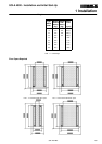
FIG.1.1.2 10-60kVA UPS floor space 4
FIG.1.1.3 80-120kVA UPS floor space 4
FIG.1.1.4 AC001 transformer cabinet 4
FIG.1.1.5 AC002 transformer cabinet 4
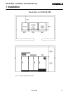
FIG.1.1.6 10-60kVA UPS room size 5
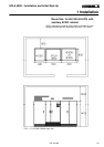
FIG.1.1.7 80-120kVA UPS room size 6
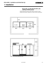
FIG.1.1.8 80-120kVA UPS room size 7
FIG.1.2.1 UPS connection diagram, version 1 9
FIG.1.2.2 UPS connection diagram, version 2 11
FIG.1.3.1 UPS connection diagram, with input
and output transformers 13
FIG.1.3.2 UPS connection diagram, with bypass
input transformer 13
FIG.1.3.3 UPS connection diagram, with THD
filters 14
FIG.1.3.4 Installation of 12-pulse units without
galvanic isolation 15
FIG.1.3.5 Installation of 12-pulse units with
galvanic isolation 15
FIG.1.4.1 External maintenance bypass switch,
version 1 16
FIG.1.4.2 External maintenance bypass switch,
version 2 17
FIG.1.6.1 Connection of remote EPO with N.C.
contact 20
FIG.1.6.2 Connection of remote EPO witn N.O.
contact 20
FIG.1.6.3 Connection of remote emergency
power off - input and battery circuit
breaker trip circuit 20
FIG.1.7.1 Connection for diesel generator
operation - syncronisation disable 21
FIG.1.7.2 Connection for diesel generator
operation - second level current
limitation 21
See Rev. Doc. JSE401547
D
23.09.97 T. Boon
See Rev. Doc. JSE401479
B
08.08.97
M. Porpora
See Rev. Doc. JSE401490
C
01.09.97
M. Porpora