


SOLA 4000 - General System Description
JUE 401264
8
1.4 Battery (Accumulator)
The battery supplies power in case of a short interruption or a total
breakdown of the ac mains supply. In case of a rectifier failure (no
dc voltage output), the load will be fed by the battery.
The battery is only capable of feeding the load for a certain time
(autonomy time), depending on battery capacity and actual load.
The number of cells within the battery depends on the battery type
and may also vary due to specific customer requirements. The
standard number is 192 cells for lead-acid batteries and 300 cells
for NiCd batteries. The battery capacity (Ah) depends on the UPS
output power and the required autonomy time. The battery of 10-
30kVA units is installed inside the UPS cabinet as standard. For
40-120kVA units (or 10-30kVA units with extended battery au-
tonomy), batteries are installed in external battery cabinets.
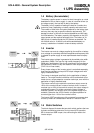
1.5 Inverter
The inverter converts dc voltage supplied by the rectifier or battery
to ac voltage of a precisely stabilised amplitude and frequency that
is suitable for power supply to most sophisticated electrical equip-
ment.
The inverter output voltage is generated by sinusoidal pulse width
modulation (PWM). The use of a high carrier frequency for the
PWM and a dedicated ac filter circuit consisting of the transformer
and capacitors, ensure a very low distortion of the output voltage
(THD<1% on linear loads).
Every phase voltage of the inverter output is controlled separately,
thus ensuring constant and equal UPS output voltages even with
highly unbalanced loads.
The inverter is designed specifically for the application of today's
loads i.e. The output harmonic distortion will be maintained at low
levels due to a unique adaptive correction technique, even with the
application of highly distorted loads.
The inverter control logic restricts the maximum output current to
150% of the nominal current in case of a short circuit. In case of
overload (up to 125% of the nominal current), the output voltage is
maintained constant. For higher currents the output voltage is
reduced, however, this will only occur if the bypass supply is not
available. Otherwise the UPS will switch to bypass operation for
currents higher than 110% of the nominal current.
The inverter IGBT transistors are fully protected from severe short
circuits by means of a desaturation monitor or "electronic fuse".
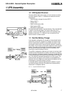
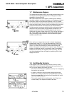
1.6 Static Switches
The block diagram illustrates the two static switch sections that use
thyristors as switching elements. During normal UPS operation,
SSI is closed and SSB is open, thus connecting the load to the
inverter output.
1 UPS Assembly