


SOLA 4000 - Operating Panel
ISSUED
A4 191
JUE 401267
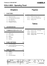
Chapters
1 FUNCTIONS 2
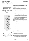
1.1 Indication of Important Data 2
1.2 Battery Monitoring 2
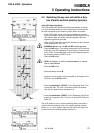
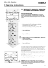
1.3 UPS Operating Mode Indication 3
1.4 Alarm Signalling 3
1.5 Remote Monitoring 3
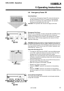
1.6 Emergency Power Off 4
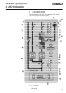
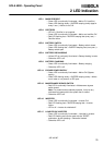
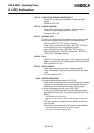
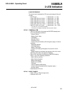
2 LED INDICATION 5
3 COMMUNICATION WITH A PC 9
3.1 Connection to PC 9
3.2 SNMP mode 10
3.3 Service Mode 10
3.4 Alarms 11
3.5 UPS status 13
3.6 Metering 13
4 PANEL SETTINGS 14
4.1 DIP Switch Settings 14
4.2 Location of DIP switches and pushbuttons
on the CPU/NCP pcb 16
5 REMOTE PANEL 17
5.1 General 17
5.2 Installation 17
5.3 Functions 18
5.4 DIP-switch settings 19
Contents of JUE 401267
M. Porpora
T. Boon
04.02.97
04.02.97
Figures
FIG. 2.1 LED Indication 5
FIG. 3.1 RS232 connection cable 9
FIG. 4.3 Layout of the CPU/NCP pcb 16
FIG. 5.1 Setting of DIP1 19
Tables
TAB 4.1 Setting of SW1 - UPS rating 14
TAB 4.2 Setting of SW1 14
TAB 4.3 Setting of SW1 - Nominal Voltage 14
TAB 4.4 Setting of SW2 15
We reserve the right to modify the contents of this document without notice. BEST POWER- BORRI ELETTRONICA INDUSTRIALE S.r.l Via 8 Marzo Soci, Bibbiena (AREZZO)
A
See Rev. Doc. JSE 401440 20.06.97
T. Boon
B
See Rev. Doc. JSE 401490
01.09.97
M. Porpora