


SOLA 4000 - PCB Description
JUE 401268
98
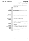
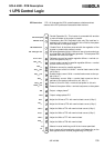
- Proportional to the inv. voltage. 6V ≡ nominal inverter voltage
- Inv. voltage tolerance adjust for 6V at TP1 with nom. voltage
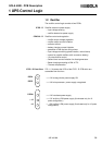
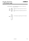
- Push to switch ON the inverter output static switch (SSI)
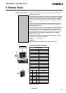
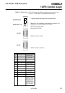
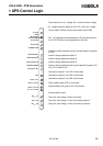
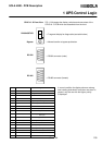
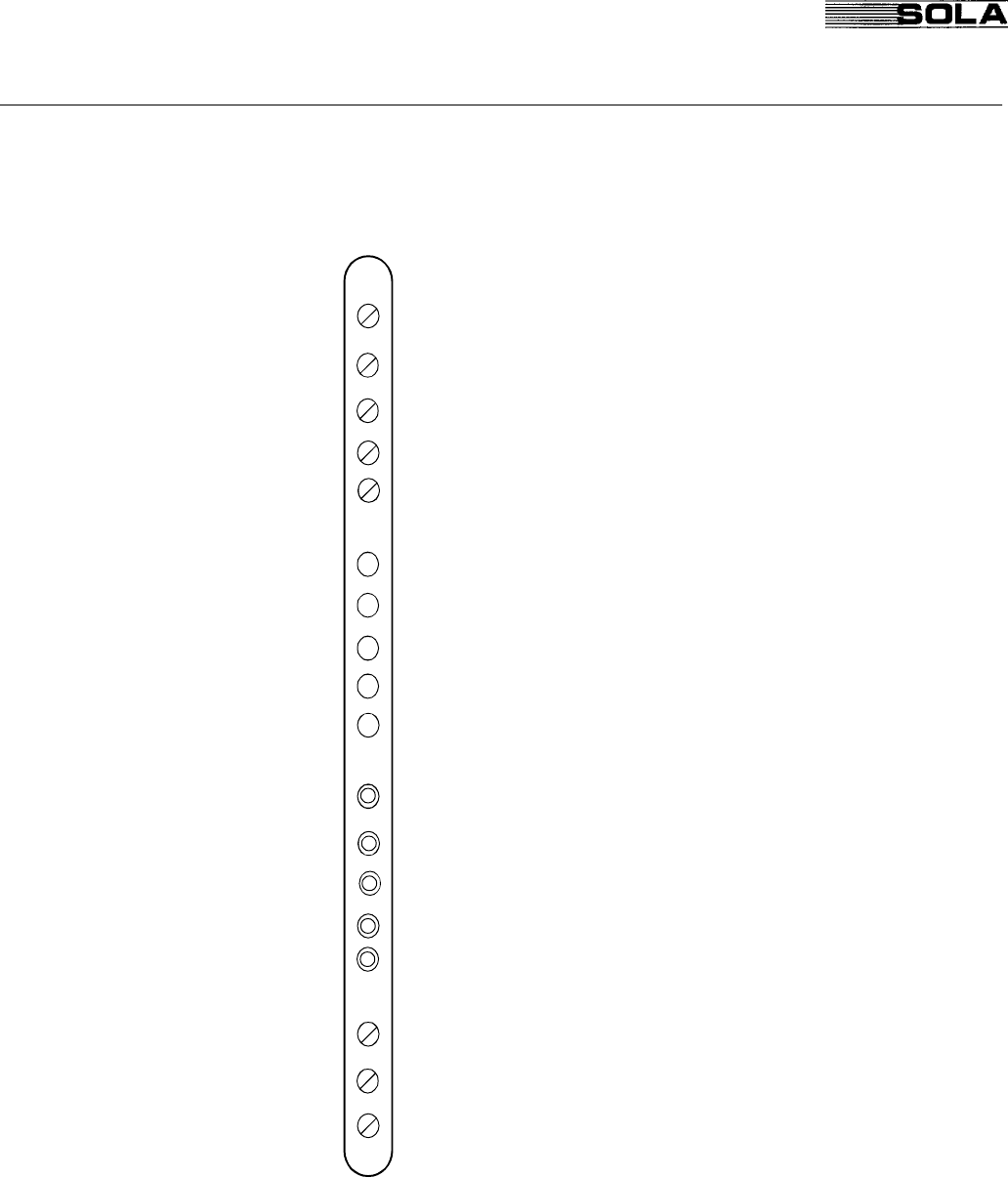
ICT-2 Front View FIG. 1.4 illustrates the potentiometers, LEDs and test points of
the ICT-2 PCB which are accessible from the front.
- Frequency offset adjustment (when synchronisation is blocked
at TP5)
- Inverter voltage adjustment phase T
- Inverter voltage adjustment phase S
- Inverter voltage adjustment phase R
- Inverter voltage adjustment during test operation (jumpers JP1,
JP2, JP3 in position 2,3)
- Overload on phase T: red LED is illuminated
- Overload on phase S: red LED is illuminated
- Overload on phase R: red LED is illuminated
- Pulse release: green LED is illuminated
- Synchronisation OK: green LED is illuminated
- Synchronisation block
- Test point: test voltage = 6Vdc at full load
- Test point: test voltage = 4Vdc at full load on phase T
- Test point: test voltage = 4Vdc at full load on phase S
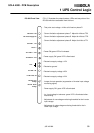
1 UPS Control Logic
P1 Freq.
Offset
LD4 Overload Φ S
LD3 Overload Φ R
LD1 Synch. OK
LD5 Overload Φ
T
TP1 I
nom
= 4V ΦR
TP2 I
nom
= 4V ΦS
LD2 Pulse Release
TP4 I
nom
= 6V
TP3 I
nom
= 4V ΦT
P7 I
nom
ΦS
P6 I
nom
ΦR
P8 I
nom
ΦT
P5 ΦT Volts
P4 ΦS Volts
P3 ΦR Volts
P2 Manual Test
TP5