


Chapters
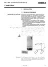
1 UPS ASSEMBLY 2
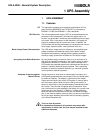
1.1 Features 2
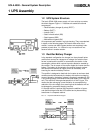
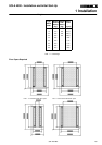
1.2 UPS System Structure 3
1.3 Rectifier/Battery Charger 3
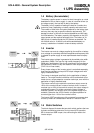
1.4 Battery (Accumulator) 4
1.5 Inverter 4
1.6 Static Switches 4
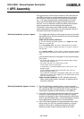
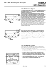
1.7 Maintenance Bypass 6
1.8 Hot-Standby Systems 6
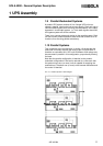
1.9 Parallel-Redundant Systems 7
1.10 Parallel Systems 7
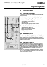
2 OPERATING PANEL 8
2.1 Functional Description 8
2.2 Remote Monitoring 8
2.3 Emergency Power Off 8
Figures
FIG. 1.1 UPS Block-Diagram 3
FIG. 1.2 Rectifier Block-Diagram 3
FIG. 1.3 12-Pulse Rectifier Block-Diagram 3
FIG. 1.4 Inverter Block-Diagram 4
FIG. 1.5 Static Switches Block-Diagram 4
FIG. 1.6 Maintenance Bypass Block-Diagram 6
FIG. 1.6.1 Wall-mounted Maintenance Bypass
Block-Diagram 6
FIG. 1.7 Hot-Standby Operation Block-Diagram
6
FIG. 1.8 Parallel Operation Block-Diagram 7
FIG. 2.1 SOLA 4000 Operating Panel 8
SOLA 4000 - General System Description
Contents of JUE 401264
ISSUED
A4 81
JUE 401264
04.02.97M. Porpora
T. Boon
04.02.97
We reserve the right to modify the contents of this document without notice. BEST POWER- BORRI ELETTRONICA INDUSTRIALE S.r.l Via 8 Marzo Soci, Bibbiena (AREZZO)
See Rev. Doc. JSE401440A 20.06.97 T. Boon