


SOLA 4000 - PCB Description
JUE 401268
97
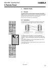
Inverter control and regulation (parallel configuration)
• parallel regulation of up to 8 inverters
• system control for up to 8 inverters (together with ICP pcb)
• cold-standby control
• load monitoring
• redundancy monitoring
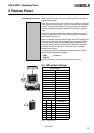
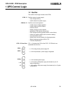
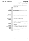
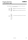
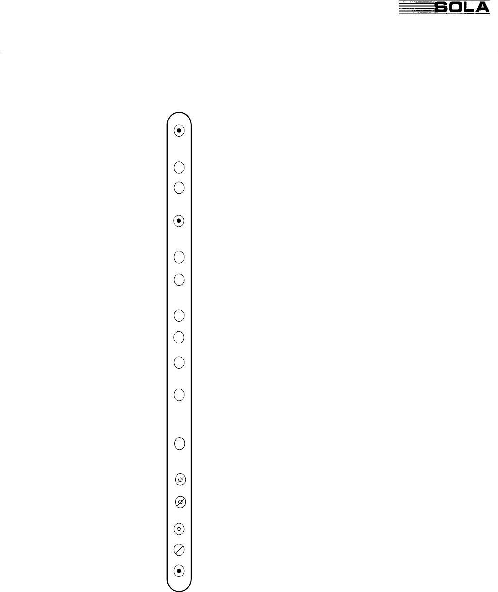
ICP Front View FIG. 1.3 illustrates the LEDs and switches of the ICP PCB which
are accessible from the front.
- Push to switch the inverter ON/OFF
- Inv. electronic power supply in order: green LED is illuminated
- Defect in the internal quartz oscillator: red LED is illuminated
- RESET
- Inverter in order: green LED is illuminated
- Inv. voltage within tolerance (within +/- 10% of Vnom): green
LED is illuminated
- Retransfer to inv. operation is blocked after 5 attempts within 3
minutes: red LED is illuminated
- Overtemperature within the inv. section: red LED is illuminated
- The inverter static switch has failed to switch ON/OFF: red LED
is illuminated
- All conditions are in order for a retransfer of the load to the inv.
(for hot-standby units, the inv. is ready in case of a failure to
the on-line inv.): green LED is illuminated
- A failure within the monitoring of the output switch: red LED is
illuminated
- Disable the quartz oscillator
- Disable inverter voltage monitoring
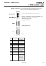
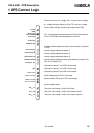
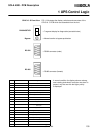
1 UPS Control Logic
PB2 Inv. ON / OFF
LD1 PSP OK
LD3 Osc. Failure
PB1 Reset
LD6 Inverter ready
LD7 IUG failure
S1 Osc. Block.
S2 Inverter Monit. Block.
PB3 SSI ON
TP1 INV. Volts
Vnom=6V
LD9 Inverter OK
LD8 Inverter volts OK
LD2 Retr. blocked
LD4 Overtemperature
LD5 SSI failure
P1 INV. Volts
tol.adjust