


SOLA 4000 - Installation and Initial Start-Up
JUE 401265
29
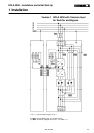
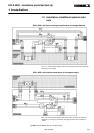
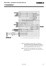
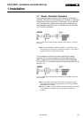
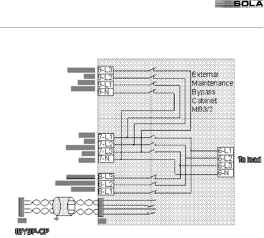
FIG.1.4.2 External Maintenance Bypass Switch Version 2 (3 position)
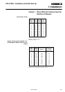
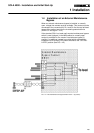
Note1: For Hot-Standby or parallel systems, it is sufficient to
feed one contact into one unit only, however they may be
connected in parallel at M4 (of IBYBP-CP) Pin1 and Pin 2 for
all units. In this case separate terminals may be provided
within the MB3 cabinet (see FIG. 1.9.2 and 1.10.2)
Note2: The cable used must be twisted pair, with a total shield.
This shield must be grounded at one end (the cabinet of the
UPS may be used).
1 Installation