


SOLA 4000 - Installation and Initial Start-Up
JUE 401265
32
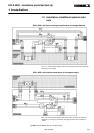
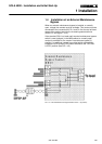
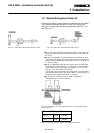
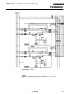
1.6 Remote Emergency Power off
A Remote Emergency Power Off may be connected to the system.
The connection terminals are M4 Pin 5 and Pin 6, using a nor-
mally-open, voltage-free contact as a pushbutton.(See FIG. 1.6.1.
and FIG 1.6.2.)
FIG. 1.6.1 Connection of Remote EPO with N.C. contact FIG. 1.6.2 Connection of Remote EPO with N.O. contact
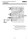
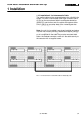
Note 1: The cable used must be twisted pair, with a total shield. This
shield must be grounded at one end (the cabinet of the UPS may
be used).
Note 2: For Hot-Standby or parallel systems, it is sufficient to feed
one contact into one unit only, however they may be connected in
parallel at M4 (of IBYBP-CP) Pin5 and Pin 6 for all units (N/O) only
or series for (N/C).
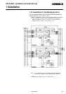
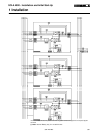
Note 3: To completely isolate the UPS system from all voltage with
the emergency power off (EPO), it is necessary to install trippable
circuit breaker on the input supply (to terminals 1-L1, 1-L2, 1-L3
and 4-L1, 4-L2, 4-L3 and 4-N if installed).
The trip coil is then connected to the terminal M1 on the CPU/NCP
pcb located inside the front door of the cabinet. A normally open or
normally closed voltage-free contact is available.
Note 4: The N.C. contact can only be used for IBYBP-CP
motherboards in rev. 0A and following.
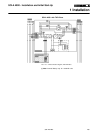
FIG. 1.6.3 Connection of Remote Emergency Power Off - Input and battery circuit
breaker trip circuit.
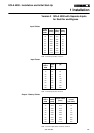
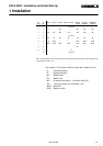
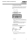
Nominal Rating of Contacts
125 V
≅
0,5 A 60 W
30 V
≅
2 A 60 W
TAB. 1.6.1 Nominal Rating of contacts for the input breaker trip circuit.
1 Installation