


SOLA 4000 - PCB Description
JUE 401268
96
1 UPS Control Logic
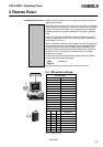
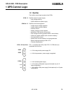
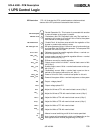
In normal condition the display shows a red seg-
ment rotating clockwise. During the starting phase,
a blinking central segment "-" is displayed. During
parameter acquisition through the serial interface,
the character "A" is displayed. If more than one
alarm is present, only the one with the higher
priority is displayed.
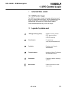
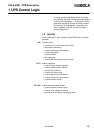
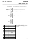
1.3 Inverter
The inverter control logic consists of three PCBs (four for parallel
systems).
ICP Inverter control
• control for the inverter static switch (SSI)
• temperature monitoring
• inverter monitoring and protection
• hot-standby control
• quartz oscillator
• fan monitoring
• inverter electronic power supply monitor
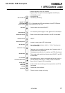
ICT-2 Inverter regulation
• inverter output voltage regulation
• inverter output current limitation
• short-circuit protection
• inverter soft start control
• inverter-bypass synchronisation
• inverter-oscillator synchronisation
• synchronisation monitor:
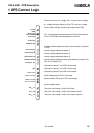
IPS - 500 Inverter electronic power supply
• inverter electronic power supply
• inverter input voltage monitoring
• generation of the battery-discharging alarm