


SOLA 4000 - Installation and Initial Start-Up
JUE 401265
54
3 ADDITIONAL START-UP PROCED. FOR
MULTI-UNIT SYSTEMS
3.1 Start-Up Procedure for Hot -standby Sys-
tems
Repeat the procedure of section 2 for the second unit in the system
(with the first unit off).
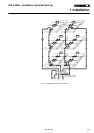
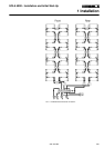
Ensure that the interconnecting BUS cable is connected according
to section 1.9.1 and FIG 1.9.3.
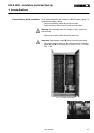
J • Switch off the inverter at the second unit with PB2 at the top of
the ICP pcb. The unit will transfer to the bypass supply.
• Switch on IRP of the first unit.
• Ensure that the switch IUG of this unit is off.
• Switch on IRE of the first unit.
After approx. 10 seconds the display will flash with a "U" indica-
tion and static bypass switch SSB will be closed.
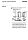
• Measure across the output switch IUG from input to output of
each phase.
?
Is this voltage less than 2V a.c for all three phases?
no The output power interconnections are incorrect and must be
reconnected correctly. Switch off both units and the mains
supply and recheck the connections.Return to J
yes Continue
• Close IUG of the first unit. The two static bypasses (SSB) are
now connected in parallel.
• Close the battery switch of the first unit.
• Start the unit by pressing "START" on the front operating panel.
when the inverter is synchronised, the unit will transfer the
inverter to the output (SSI closes and both SSB switches switch
off).
• Press "START" on the operating panel of the second unit.
The inverter will start and become ready (check that the green LED
LD6 on the ICP pcb is illuminated) but the static switch SSI will not
close.
• Check the commutation of the inverters by pressing PB2 at the
top of the ICP pcb on the unit currently with SSI closed.
• Restart the inverters (with PB2 on ICP or with "START").
THE SYSTEM IS NOW IN NORMAL OPERATION AND THE HOT-STANDBY START-UP
HAS BEEN SUCCESSFULLY COMPLETED.
3 Additional Start-Up Proced. for Multi-Unit Systems