


JUE 401267
75
SOLA 4000 - Operating Panel
1 Functions
1.3 UPS Operating Mode Indication
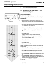
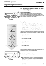
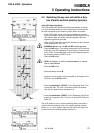
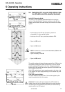
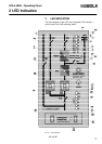
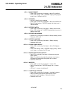
On the operating panel a block diagram of the UPS is shown. The
operating mode of the UPS is indicated with LEDs integrated into
the block diagram.
LED Off If a LED is not illuminated at all, the corresponding section is not
active.
LED On, Green
If a LED is continually illuminated (green), the corresponding
section is o.k.
LED Flashing, Green If a LED is flashing (green), the corresponding section is not o.k.,
but the power supply to the load is not currently endangered.
LED On, Yellow The corresponding section is OK, but it is not the nominal working
condition of UPS.
LED Flashing, Red If a LED is flashing (red), the corresponding section is not o.k., and
the power supply to the load is endangered.
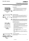
1.4 Alarm signalling
By the UPS Alarms are signalled by the UPS using LEDs and an audible alarm:
• Status LEDs signal an alarm by flashing.
• The integrated buzzer signals an alarm by beeping.
• The buzzer can be muted by pressing "Alarm Reset" at the
operating Panel. The LEDs continue flashing when the alarm
condition is still active.
There are two different types of alarm signals:
• The flashing LED is green and the buzzer beeps slowly if the
power supply to the load is not currently endangered (common
alarm flashing - yellow).
• The flashing LED is red and the buzzer beeps fast if the power
supply to the load is endangered (common alarm is flashing
red).
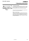
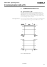
1.5 Remote Monitoring
The operating panel provides an option to communicate with a
computer through RS232 and RS485 interfaces. The RS232 serial
interface communicates with a PC or mainframe computer, with a
SNMP protocol (SEC). With the RS485 interface it is possible to
transmit all necessary data up to a distance of 400m or to connect
a remote monitoring panel.