


SOLA 4000 - Operation
JUE 401266
70
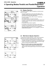
5 Operating Instructions
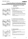
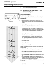
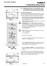
5.3 Switching On any one unit within a Sys-
tem (Parallel and Hot-standby Systems)
Initial UPS Operating Mode
The UPS module was switched off using the procedure in section
5.4, all of the power switches in this module are in the off position,
the load is supplied by the remaining unit(s) within the system.
• If this UPS module has an input supply separate to the other
units in the system, switch on the external mains supply for this
UPS module; both the rectifier input and bypass input when
separate supplies are provided.
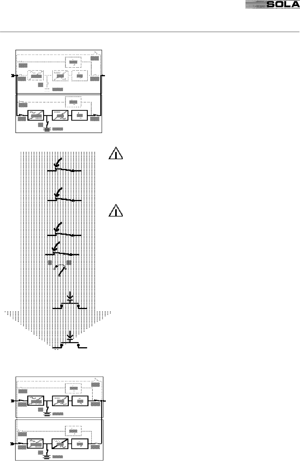
• Open the UPS front door, or the part necessary to allow access
to the switches IRP, IRE, IUG.
• WARNING: ENSURE THAT THE IUG AND IRE SWITCHES ARE OPEN.
IRP: • Close the IRP switch. The rectifier starts and the UPS performs
a self test. The UPS Operating Panel will beep 3 times and test
all the LEDs. The audible alarm may continue beeping and can
be muted by pressing "RESET" once.
IUG: • Close the IUG switch.
• NOTE: IN ORDER NOT TO AFFECT SYSTEM PERFORMANCE, IT IS IMPOR-
TANT TO CLOSE IUG NOW.
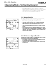
IRE:
• Close the IRE switch.
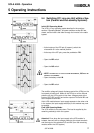
IB:
• Close the battery switch IB.
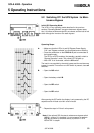
IPR: S1
• If present, ensure that the micro switch S1 at the bottom of the
IPR pcb is in the AUTO position.
START: • Press the pushbutton "START" on the Operating Panel. The
inverter will start. The LED 16 will flash red and 10 seconds
later will turn green and be permanently lit.
RESET: • Press the pushbutton "RESET" on the Operating Panel.If not
already on, the green LED 17 will turn on and the LED 29 must
switch off.
The UPS module is now in normal operating mode, connected in
parallel with the remaining units in the system (parallel systems,
section 4.1 or 4.2) or ready to take over the load in the case of an
inverter failure (hot-standby systems, section 3.1)
.