


SOLA 4000 - Installation and Initial Start-Up
JUE 401265
51
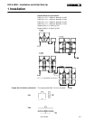
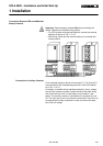
B: Inverter Voltage Adjustment • On the SS/FY pcb, measure the voltage at the screws Inverter
R, Inverter S, Inverter T with respect to the neutral terminal 5-
N.
?
Does this voltage correspond to the desired voltage?
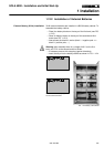
no • Adjust the voltage to the desired value individually for each
phase using P3, P4 and P5 on the ICT-2 pcb.
NOTE: If the inverter output voltage is changed, the value at
TP1 (adjusted with P1) on the ICP pcb should be checked. (6V
corresponds to nominal voltage). Note also that for parallel
systems, if the voltage is changed here, the current sharing will
also be affected. Therefore, change voltage settings ONLY IF
ABSOLUTELY NECESSARY. Small variations of the voltage will not
affect system performance. The UPS is already pre-calibrated
in the factory with nominal load.
yes • Continue with C
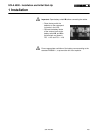
C: Inverter free-run frequency check • Insert a pin d=2mm in the red test point S1 on the ICP pcb. The
red LED LD3 on the ICP pcb must be permanently lit. The
inverter frequency is now free-running without the internal
oscillator.
• On the SS/FY pcb, measure the inverter frequency on the
screws Inverter R, S or T with respect to neutral.
• Check that the frequency is set at the required value (50/60 Hz
+/- 0,1 Hz). It can be adjusted with P1 on the ICT-2 pcb. Re-
move the pin from S1. The inverter now synchronises with the
internal oscillator.
• Make sure that the batteries have been installed according to
the instructions for installation.
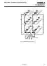
With an external battery cabinet B3/38:
• Measure the battery voltage in the battery cabinet at the battery
switch between cables:
- -290 (-) and -1 (+)
- +1 (-) and +4 (+)
With an external battery cabinet B3/65:
• Measure the battery voltage in the battery cabinet at the battery
switch between cables:
- -290 (-) and -1 (+)
- +1 (-) and +2 (+)
?
Does this voltage have positive polarity?
no • Open IRP, wait for 5-10 minutes, and then reconnect the
battery cables at the terminals which lead to the switch(es)
where the wrong polarity was detected.
• Return to D.
yes • Check the voltage between the battery terminals B+ and B-.
The value of this voltage should be already set according to the
amount of batteries installed.
• Close battery switch IB.
The alarm "battery switch open" stops.
2 Initial Start-Up