


SOLA 4000 - Operation
JUE 401266
72
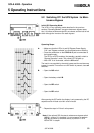
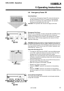
5.5 Emergency Power Off
Operating Steps:
• To activate the Emergency Power Off, press simultaneously
the two pushbuttons in the E.P.O. section of the operating
panel (For hot-standby and parallel systems, the operation
needs to be performed at one unit only).
Attention! This operation will remove all supply to the load.
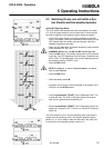
Emergency Shut Down:
When E.P.O. is activated, all static switches SSI and SSB and the
battery switch(es) IB (when connected with a trip circuit) are
opened, the rectifier(s) and inverter(s) are switched off. The Data
Monitor Panel / NCP will lose supply when the internal DC filter
capacitors discharge.
Attention! Although the load is no longer supplied by the UPS, the
input and output switches are still closed. Voltage is still present in
the UPS unless the input circuit breaker(s) have a shunt trip circuit
connected with the EPO circuit (see JUE 401066 "Installation and
Initial Start-up", section 1.5).
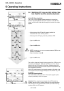
Reset after Activating E.P.O.
RESET:
• To restart the UPS press the RESET push-button PL2 located
on the CPU / NCP pcb inside the front door of the UPS. This
releases the EPO circuit and the rectifier will restart.
Note that if the input switch(es) were automatically tripped, it is
sufficient to reclose the switch(es) without the need to press the
reset pushbutton above.
• Press the pushbutton at the front of the CPHC16-R pcb at the
right side of the UPS control electronic.
IB: • After the front panel is illuminated, close IB.
• Repeat for all units in the system.
• Press the "RESET" button for one second on the operating
panel.
• Press the "START" button for one second on the operating
panel and repeat for all units in the system (if multiple units are
present).
Final UPS Operating Mode:
The UPS is returned to normal operation, and all power switches
except IBY are closed.
5 Operating Instructions