


SOLA 4000 - Installation and Initial Start-Up
JUE 401265
50
2 INITIAL START-UP
2.1 Start-Up Procedure
General
With the Start-Up procedure the correct installation of the UPS
according to the previous section is checked. It must be carried out
by specialised personnel.
Safety precautions according to the appropriate local safety stand-
ards must be applied.
Should problems arise during the Start-Up Procedure, call for
service assistance.
Preparation
For carrying out the Start-Up Procedure you need a 3 1/2 digit
voltmeter with 1% accuracy, an AC/DC clip-on ammeter and a
small screwdriver for potentiometers (only when necessary).
The installation of the UPS must have been carried out according
to the previous section.
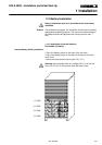
• Check that the ventilation system of the UPS room is ready to
operate.
• Check that all switches IRP, IRE, IUG, IBY, IB are open and
the load is off.
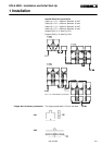
A: Rectifier Power Supply Check • Switch on the external mains supply to the UPS.
• Check that the supply voltage at terminals 1-L1, 1-L2, 1-L3 is
within ±10% of the UPS rated voltage.
• Close IRP.
?
Does the display on the CPHC16 -R pcb for the rectifier give the
indication "P"?
yes The phase rotation at the input is incorrect.
• Open IRP, switch off the external mains supply and exchange
any two of the cables at input terminals 1-L1, 1-L2, 1-L3.
• Return to A.
no The rectifier supply voltage is o.k. and the rectifier will automati-
cally start to operate.
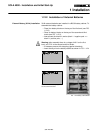
• Wait until the Data Monitor Panel / NCP is illuminated
• Press the START push-button on the front of panel (or the push
button PB2 on the top of ICP card) the inverter will start and
after approximately 10s the green led L16 will be permanently
lit.
• Press the push-button PB3 on the bottom of ICP card:
after few seconds the three green leds on SS/FY card will be lit.
One led is flashing:
- green LED 3 flashing: "Battery switch open". Note that when
using the external battery cabinet this function is desabled.
NOTE: If the battery switch indication is not blinking then the connections to C1
and C2 in the battery cabinet are not correct. Refer to the section "Installation".
2 Initial Start-Up