


SOLA 4000 - Installation and Initial Start-Up
JUE 401265
14
SOLA 4000 - Installation and Initial Start-Up
FIG.1.8.1 Connec. of remote common alarm 22
Figures
FIG.1.9.1 Connection of remote reset 22
FIG.1.10.1Interconnection of hot-standby units
with integrated maintenance bypasses
and separate bypass terminals 23
FIG.1.10.2Interconnection of hot-standby units
with external maintenance bypass and
separate bypass terminals. 24
FIG.1.10.3Interconnection of control BUS cable
for hot-standby units 25
FIG.1.11.1Interconnection of parallel units with
integrated maintenance bypasses and
separate bypass terminals. 27
FIG.1.11.2Interconnection of parallel units with
common maintenance bypass and
separate bypass terminals 28
FIG.1.11.3Location of connectors on the
IBYBP-CP pcb 29
FIG.1.11.4Interconnection of control BUS cables
between parallel units 29
FIG.1.12.1Internal battery connections 31
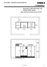
FIG.1.12.2B3/38: battery tray in the first level 32
FIG.1.12.3B3/38: batt. trays in the second and the
third level 32
FIG.1.12.4Battery cabinet B3/38 32
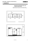
FIG.1.12.5B3/38:switch IB and terminals 33
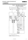
FIG.1.12.6B3/38 internal electrical connec. 34
FIG.1.12.7Battery cabinet B3/65 35
FIG.1.12.8B3/65:switch IB and terminals 35
FIG.1.12.9B3/65 internal electrical connec. 36
FIG.1.12.10UPS with additional batt. cabinet 37