


SOLA 4000 - PCB Description
JUE 401268
95
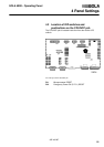
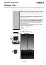
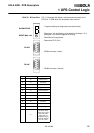
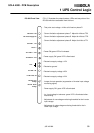
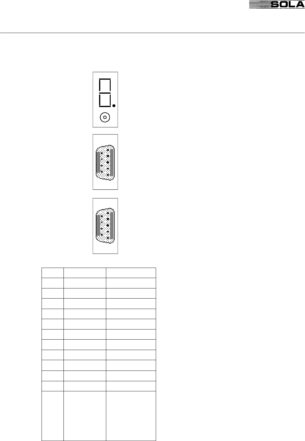
CPHC16 - R Front View FIG. 1.2 illustrates the display, switches and connectors of the
CPHC16 - R PCB which are accessible from the front.
- 7 segment display for diagnostics (see table below)
- Reset max. Vdc pushbutton: press when the character "4" is
displayed or the central segment is blinking.
- Reset Boost Charge Alarm
- Reset after EPO (V2.1)
- RS232 connector (male)
- RS485 connector (female)
1 UPS Control Logic
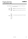
DIAGNOSTICS
RESET MAX. Vdc
RS 232
RS 485
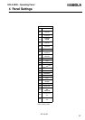
Priority Indication Diagnostics
1 8 E²PROM failure
2 2 Fuse blown
3 C Mains not OK
4 P Wrong phase rotation
5 3 Overtemperature
6 4 Overvoltage
7 Ø Pulse release missing
8 9 Rectifier failure
9 6 Fan failure
10 L Overload
-- Boost charge
"--"
(when blinking)
Has left the boost
charge due to a given
time limit but the
battery was not
completely charged.
Reset with "RESET
max. Vdc" above.