


SOLA 4000 - Installation and Initial Start-Up
JUE 401265
34
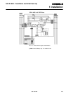
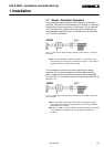
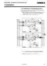
1.8 Common Alarm Contacts
As a standard feature, contacts are provided for a remote common
alarm.The connector is located on the control p.c.b for the front
operating panel (CPU/NCP), located inside the front door of the
UPS.
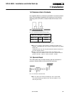
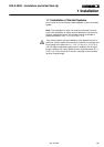
FIG. 1.8.1 Connection of Remote Common Alarm
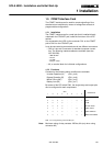
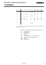
Nominal Rating of Contacts
125 V
≅
0,5 A 60 W
30 V
≅
2 A 60 W
TAB. 1.8.1 Nominal Rating of contacts for the common alarm.
Note 1: As an option a pcb CP-NET is available, providing more
contacts, compatible with most common configurations (eg AS400,
Novell etc.)
A Remote panel may also be purchased with identical functions to
the front operating panel.
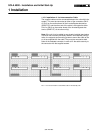
Note 2: To achieve a single common alarm for parallel or hot-
standby units, the contacts of each unit may be interconnected in
parallel (normally - open) or series (normally - closed).
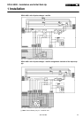
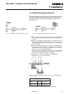
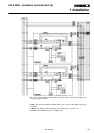
1.9 Remote Reset
The UPS system may be reset remotely with the connection of
contacts ( a push-button) to the terminal M4 as shown:
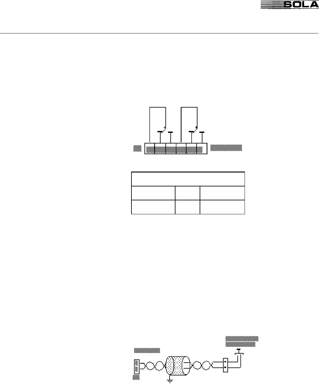
FIG.1.9.1 Connection of Remote Reset
Note: The cable used must be twisted pair, with a total shield.
This shield must be grounded at one end (the cabinet of the
UPS may be used).
1 Installation