


SOLA 4000 - PCB Description
JUE 401268
99
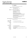
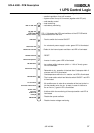
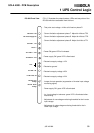
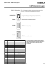
- Test point: test voltage = 4Vdc at full load on phase R
- Current limitation adjustment phase T. Adjust for 4Vdc at TP3
- Current limitation adjustment phase S. Adjust for 4Vdc at TP2
- Current limitation adjustment phase R. Adjust for 4Vdc at TP1
- Power ON:green LED is illuminated
- Power supply OK: green LED is illuminated
- Electronics supply voltage +12V
- Electronics ground
- Electronics supply voltage +26V
- Electronics supply voltage +24V
- Jumper for test operation (suppression of inverter input voltage
monitoring signal)
- Power supply OK: green LED is illuminated
- Inv. input voltage in tolerance: green LED is illuminated other-
wise blinking
- Adjustment of overvoltage monitoring threshold for the inverter
input voltage.
- Adjustment of undervoltage monitoring threshold for the in-
verter input voltage.
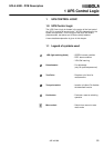
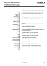
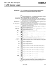
1 UPS Control Logic
LAS Power - ON
DF1 Power Supply OK
TP15 PSP +12V
TP3 0 V
TP17 PSP-1 + 26V
TP18 PSP-A + 24V
Test
LUV PSP OK
LVI DC Volts OK
RV4 DC Over
Voltage
RV3 DC Under
Voltage
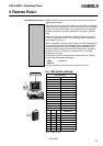
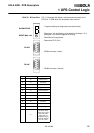
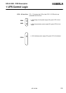
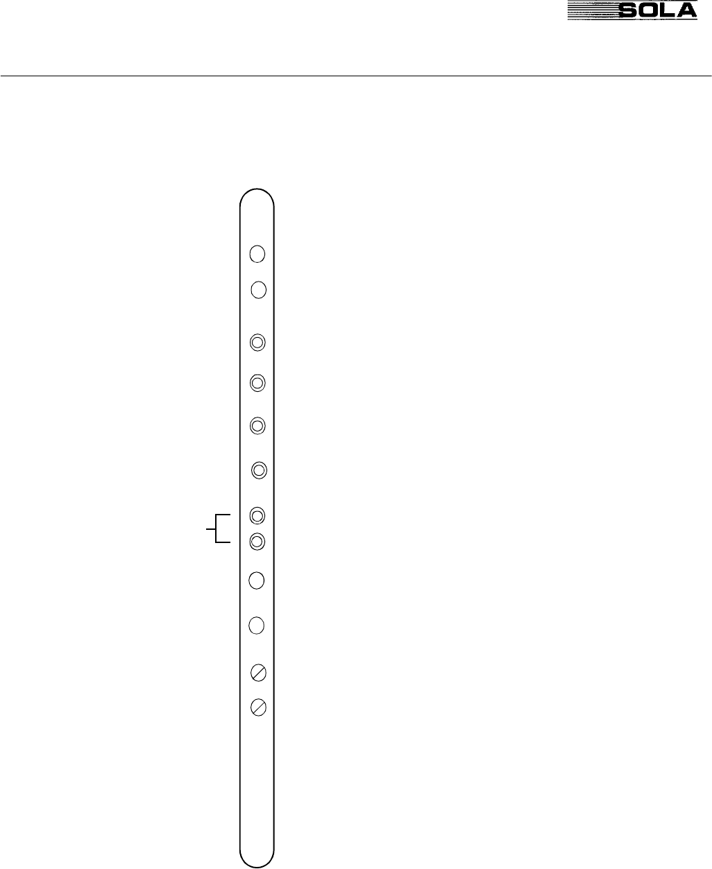
IPS-500 Front View FIG. 1.5 illustrates the potentiometers, LEDs and test points of the
IPS-500 which are accessible from the front.