


SOLA 4000 - Installation and Initial Start-Up
JUE 401265
41
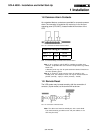
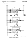
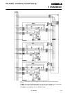
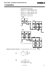
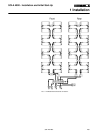
1.11.1 Installation of the Interconnection Cables
There are two interconnection cables supplied with the units for
each additional unit to the first unit. These cables must be con-
nected between the units as shown in FIG. 1.11.4 One cable is
connected to either CN12 or CN13 (the other end being connected
to the corresponding connector of another unit), and the other
cable is connected to either of CN10 or CN11, again with the other
end connected to the corresponding connector of another unit. In
this way, all units will be interconnected by two cables in a BUS-
Communication system (Daisy-chain connection).
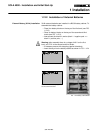
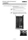
Note: If the unit is to be added to one already installed stand-alone
unit which has not been previously tested in a parallel configura-
tion, the supports and mounting screws to mount the cable to the
p.c.b are supplied with the cables. They must be mounted at both
sides of the selected connectors in order to fix the cables securely
to the connectors with the supplied screws.
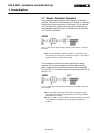
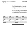
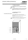
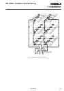
FIG. 1.11.3 Location of connectors on the IBYBP-CP pcb.
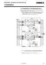
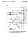
FIG. 1.11.4 Interconnection of control BUS cables between parallel units
1 Installation