


JUE 401267
84
SOLA 4000 - Operating Panel
For systems with multiple static bypasses (hot-standby and paral-
lel/redundant), if the bypass of this unit is available, but the bypass
system is not available, the UPS system cannot transfer to the
bypass supply, due to the fact that there may be insufficient by-
passes available within the system.
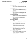
Overload The UPS is overloaded by more than the nominal output load
current
Load on Bypass The UPS system load is being supplied by the bypass supply.
Inverter not synchronised The inverter is not synchronised to the bypass supply.
Auxiliary Alarm This alarm consists of a series of system alarms and includes the
following:
• Oscillator failure
A failure has occurred in the oscillator circuit or a loss of
synchronism with another oscillator of another unit within the
system.
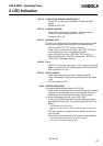
• IUG monitoring failure
An error has occurred within the monitoring circuit of the output
switch (disabled for single units).
• Static switch failure (SSI)
A failure has occurred within the monitoring circuit of the
inverter output static switch.
• Static switch failure (SSB)
A failure has occurred within the monitoring circuit of the
bypass static switch.
• Missing or incorrect bypass trip signal (parallel and hot-
standby systems)
An indifference has occurred within the bypass trip logic of this
unit and the remainder of the system.
• System not redundant (parallel /redundant systems)
If the inverter of the unit signalling this alarm fails, the system
must transfer to the bypass supply.
• SSI-ON generator failure (parallel/redundant systems)
A failure or loss of synchronism has occurred with the SSI ON
pulse generator on IPR pcb and may occur during start-up of a
unit in a parallel system. To reset press "START" and then
"RESET".
To determine which of the alarm(s) are present refer to the section
"PCB Description" JUE 401069.
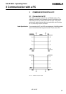
3 Communication with a PC