


SOLA 4000 - Installation and Initial Start-Up
JUE 401265
28
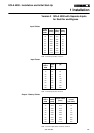
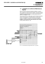
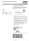
1.4 Installation of an External Maintenance
Bypass
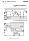
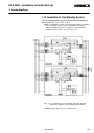
When an external maintenance bypass is installed, a normally
open, voltage free contact must be available. This contact must be
connected to the connector M4, Pin1 and Pin 2 at the top left hand
corner of the mother board for the inverter/bypass electronics
(IBYBP-CP see figure 1.10.3).
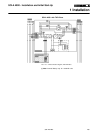
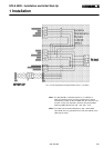
If the standard SOLA no-break wall-mounted maintenance bypass
switch is used (optional) in the MB3 cabinet, a normally open
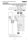
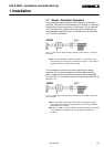
contact is provided.For the version 2 maintenance bypass (3
position), an additional contact is provided which automatically
isolates the UPS system (EPO) when switched to the "UPS ISO-
LATED" position (see FIG 1.4.2).
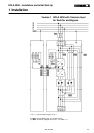
FIG.1.4.1 External Maintenance Bypass Switch Version 1 (2 position)
1 Installation