


SOLA 4000 - Installation and Initial Start-Up
JUE 401265
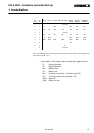
31
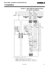
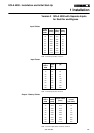
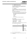
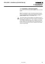
Pin
CN2
Pin
M1
AS400 NOVEL 3-COM BANYAN-VINES
BORRI
VIKING
BORRI
SIDEKICK
AMERICAN
POWER
1 1 Not Used
2 2 N - MF* - MF* MF* MF*
3 3 MF MF MF MF MF MF MF
4 4 Common
5 5 BL BL BL BL BL BL BL
6 6 B MOK - - MOK MOK MOK
7 7 BOK BOK BOK BOK BOK BOK BOK
8 8 - - - - BL* - -
9 9 0 V
10 Not Used
TAB. 1.5.2.2 Allocation of the pins for the output connectors CN1 and M1 for the various programming
configurations of TAB. 1.5.2.1
Key to table 1.5.2.2 (when contact is closed with respect to pin 4).
N: Inverter Operation
B: Bypass Operation
MF: Mains Failure
BL: Battery Low
MF*: 0V when mains failure, -12V when mains OK
BL*: -12V when battery low, otherwise +12V
MOK: Mains OK
BOK: Battery not low
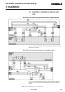
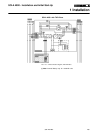
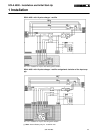
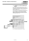
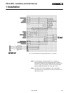
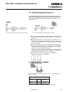
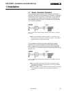
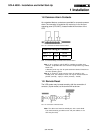
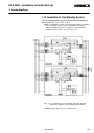
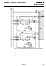
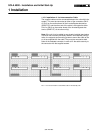
1 Installation