


5 – Maintaining the SANbox SSP
Interpreting the LED Patterns
SN0054628-00 A 5-5
Q
5. Choose option i to install the following (or the desired boot set):
t3-patch_1.1.0-15c on bootset 1
6. Choose option r to reboot.
To install a new Maintenance Mode image on SANbox SSP:
The release notes for a given SANbox SSP software release indicate whether an
update to Maintenance Mode is necessary. See the release notes for instructions
on installing the Maintenance Mode image.
5.5
Interpreting the LED Patterns
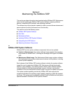
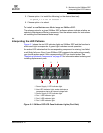
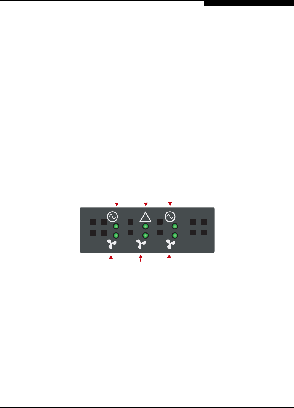
Figure 5-1 shows the six LED indicator lights on SANbox SSP and the function to
which each light corresponds. A green light indicates normal operation.
An amber LED indicates that the corresponding component is missing, has failed,
or will likely fail soon. Even if your SANbox SSPs appear to be performing normally,
you should replace parts if their corresponding LED has turned amber. See
"Replacing Hardware Components" on page 6-6 for information about ordering and
installing replacement parts.
Figure 5-1. SANbox SSP LED Panel Indicator Lights (Port Side)
1 Power Supply 1 LED indicator light.
2 Alert LED indicator light: amber indicates a
temperature alert or an internal voltage fault.
3 Power Supply 2 LED indicator light.
4 Fan 1 LED indicator light.
5 Fan 2 LED indicator light.
6 Fan 3 LED indicator light.
1
2
3
4
5
6
1 2
!
1 2 3