


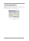
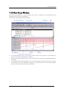

7.11.6 Display of bus information on the M32C Debugger
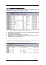
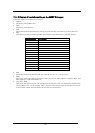
From left to right, the contents are as follows:
• Address
• The status of the address bus
• Data
The status of the data bus
• BUS
The width of the external data bus ("8b" for an 8-bit data bus, and "16b" for a 16-bit data bus)
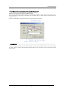
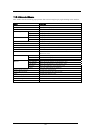
• BIU
This shows the status between the BIU (bus interface unit) and memory, and BIU and I/O.
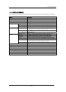
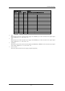
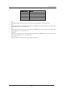
Representation
BIU statu s
- No access
WAIT Executing wait instruction
RBML Read access ytes, ML on) (b
F Fetch access
QC Discontinuous Fetch access ueue buffer) (q
RWML Read access (words, ML on)
INT Interrupt acknowledge
RB Read access (bytes)
WB Write access (bytes)
DRB Read access by DMA (bytes)
DW B Write access by DMA (bytes)
RW Read access (words)
WW Write access (words)
DRW Read access by DMA (words)
DWW Write access by DMA (words)
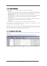
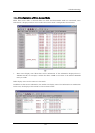
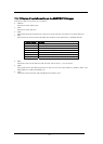
• R/W
Shows the status of the data bus ("R" for r ead, "W" for wr it e, "-" for no access).
• RWT
This signal shows the effective position in the bus cycle ("0" when effective. Address, Data, and
BIU signals are valid when RWT is "0".
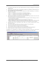
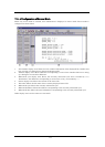
• CPU, OPC, OPR
This shows the signal between CPU and BIU. In the column "CPU", the data shows whether CPU
accesses BIU or not . In the Column "OPC", the data shows the byte size of read operat ion code.
In the Column "OPR", the data shows the byte size of read operand.
176