


5 Setup the Debugger
57
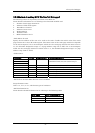
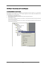
5.6.2 Method of making MCU file (the 740 Debugger)
The following content is sequentially described in the MCU file.
Please describe information on 1-4 referring to the data book on MCU used.
1. Number of stack page selection bit
2. Address of CPU mode register
3. End address of stack*1
4. Address of reset vector
5. POD number*2
6. Firmware name
7. MCU Information No.*3
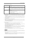
*1
End address of stack
Specify the last address of the area to be used as the stack. Consider the initial value of the stack
page selection bit in the CPU mode register. (The initial value of the stack page selection bit depends
on the microcomputer.) For a microcomputer which sets the stack page selection bit initial value to
"0", the allowable designation range is a 0 page address range (0h to FFh). For a microcomputer
which sets the stack page selection bit initial value to "1", the allowable designation range is a 1 page
address range (100h to 1FFh).
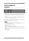
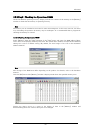
*2
POD number
Pod Name POD No. Firmwa File re Correspondence MCU
M38000T-FPD
M38000TL-FPD
M38000TL2-FPD
0 M38000 7200/7450/7470/38000/
7500Series(7507,7510,7515,7520 Group)
*4
M37207T-RPD 80 M38000 M37102,M37201,M372 2,M37204,M37207 0
M37515T-RPD 4 0 M38000 7515/3850/3 51 Group 8
M37610T-RPD 2 M37600 7610 Group
M37640T-RPD 4 M37600 7640 Group
M37690T-RPD 1 M37600 7690 Group
M38749T-RPD 40 M38000 3874Group
*4
MCU where emulator MCU does not exist is excluded.
Target firmware name
Omit "u.s", "h.s", or "l.s", which mean types of emulators.
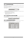
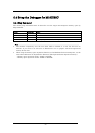
*3
MCU Information No.
Please describe the MCU information No. referring to the following tables.
MCU Name
M U Information No. C
M3753x 3754x ,M 01
M376xx 02
Others 00