


Interface Configuration and Interpretation
3-128 MTM400 MPEG Transport Stream Monitor User Manual
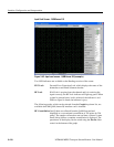
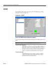
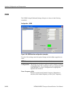
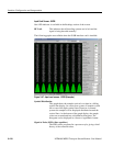
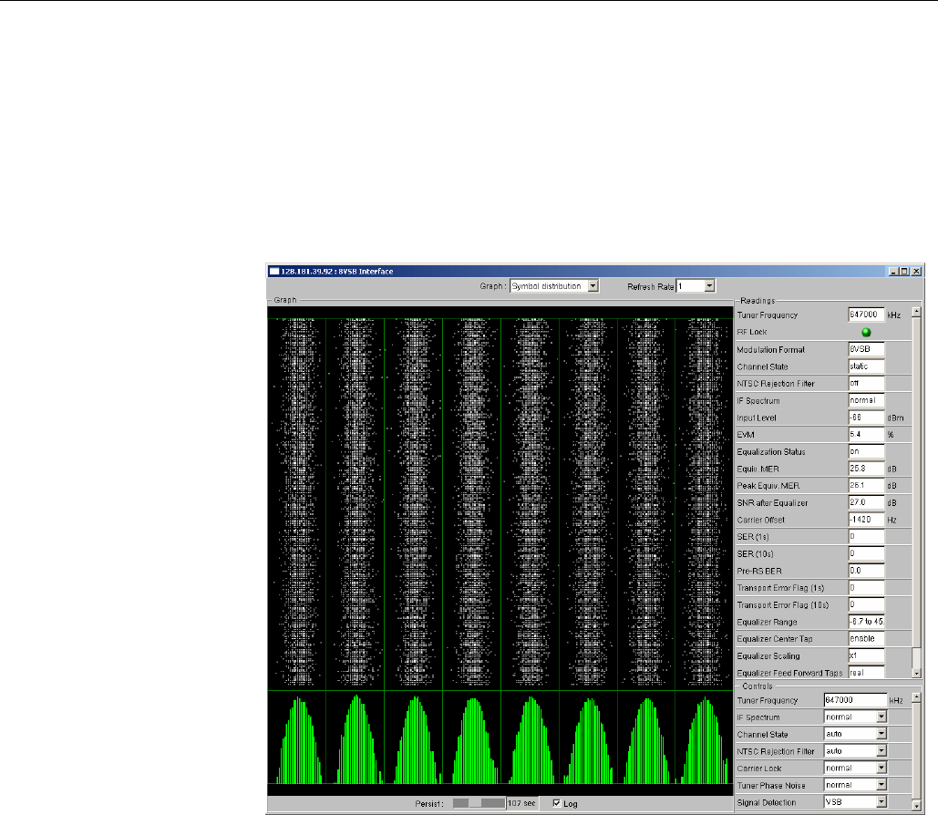
Input Card Screen - 8VSB
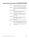
One LED indicator is available in the Readings section of the screen:
RF Lock
This indicates that all decoding systems are in lock and the
signal is being decoded normally.
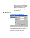
The following graphs are available when the 8VSB interface card is installed:
Figure 3-47: Input card screen - 8VSB (Example)
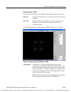
Symbol Distribution
This graph shows the samples received over time in a falling
vertical line display. In a noise-free system, all samples would
fall on one of the eight vertical lines. However, in normal
systems the samples will be displayed distributed around the
vertical lines. At the bottom of the graph display, the sample
values are accumulated into a distribution histogram. The
histogram can be displayed in a linear or logarithmic format.
Signal to Noise (SNR) (after equalizer)
The SNR values are plotted in a pen-trace style, giving a brief
history of the collected values.