


Getting Started
1-10 MTM400 MPEG Transport Stream Monitor User Manual
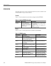
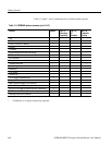
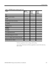
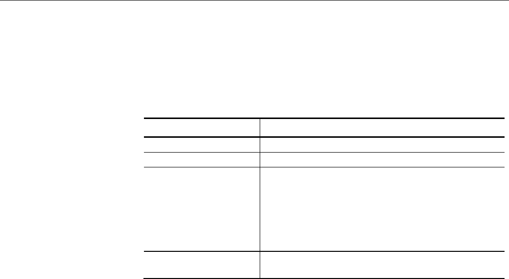
Table 1-7 summarizes the transport stream, network and peripheral device
connectors; (see the MTM400 MPEG Transport Stream Monitor Technical
Reference for more detailed information about each connector and the
associated signals).
Table 1-7: Transport stream Processor card connectors
Connector Description
Ethernet 10/100Base-T; RJ-45
LTC In Longitudinal time code input
Transport Stream input /
output
75 ohm, transformer coupled, BNC connectors for the
following signal formats:
ASI input (BNC) • Accepts Burst and Packet mode ASI formats and M2S
ASI output (BNC) • An active loop-through of the corresponding input
SMPTE310M input • Compliant with SMPTE310M (19.392 Mbps only)
SMPTE310M output • An active loop-through of the corresponding input
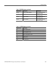
Alarms (Digital input/output) 26-pin D-type connector for alarm
relays and TTL outputs; also recording trigger input
The Alarms connector provides connections for five relays. Each relay is
configured through the user interface (see Tests Screen, page 3-23 and Custom
Screen, page 3-26); the three TTL outputs are configured in a similar manner.
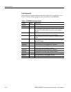
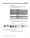
ASI Loop-Through (QAM (Annex B), COFDM, 8VSB, and 8PSK only)
To monitor ASI and RF signals, (for example, both the input and output of a
modulator):
Connect the ASI signal from the modulator to the interface card ASI In.
Connect the ASI Out terminal on the interface card to the ASI In connector
on the Transport Stream Processor card.
Select the signal to be monitored from the configuration view (see page 3-76).
The ASI signal from QAM (Annex A and C) and QPSK (L-Band) interface cards
is looped to the Transport Stream Processor card internally.