


4 Replacement Procedures
Figures
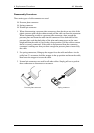
Figure 4-1 Removing the battery pack............................................................................ 4-8
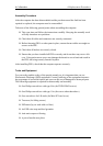
Figure 4-2 Removing the PC card ............................................................................... 4-10
Figure 4-3 Removing the SD Memory card ................................................................. 4-11
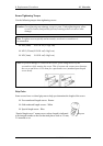
Figure 4-4 Removing memory slot cover .................................................................... 4-12
Figure 4-5 Removing the memory module .................................................................. 4-12
Figure 4-6 Removing the HDD slot cover.................................................................... 4-14
Figure 4-7 Removing the HDD ASSY ........................................................................ 4-15
Figure 4-8 Removing the HDD..................................................................................... 4-15
Figure 4-9 Removing the bottom cover........................................................................ 4-17
Figure 4-10 Removing the keyboard holder ................................................................. 4-18
Figure 4-11 Removing the bottom cover (1) ................................................................. 4-19
Figure 4-12 Removing the bottom cover (2) ................................................................. 4-20
Figure 4-13 Removing the touch pad............................................................................. 4-22
Figure 4-14 Removing the MDC board......................................................................... 4-23
Figure 4-15 Removing the HDD cable .......................................................................... 4-24
Figure 4-16 Peeling off the glass tape............................................................................ 4-25
Figure 4-17 Removing the speaker................................................................................ 4-25
Figure 4-18 Removing the RTC battery ........................................................................ 4-27
Figure 4-19 Removing the wireless LAN board(1) ....................................................... 4-28
Figure 4-20 Removing the wireless LAN board(2) ....................................................... 4-29
Figure 4-21 Removing the wireless LAN board(3) ....................................................... 4-29
Figure 4-22 Removing the PC card slot......................................................................... 4-31
Figure 4-23 Removing the LAN/MODEM jack............................................................ 4-32
Figure 4-24 Removing the sound board......................................................................... 4-33
Figure 4-25 Removing the system board (1) ................................................................. 4-34
Figure 4-26 Removing the system board (2) ................................................................. 4-35
Figure 4-27 Removing the FAN .................................................................................... 4-36
Figure 4-28 Applying silicon grease.............................................................................. 4-37
Figure 4-29 Removing the LED SW membrane............................................................ 4-38
Figure 4-30 Removing the LCD mask........................................................................... 4-39
Figure 4-31 Removing the FL inverter .......................................................................... 4-41
Figure 4-32 Removing the LCD .................................................................................... 4-42
PORTEGE R100 Maintenance Manual (960-440) 4-v