


2 Troubleshooting 2.14 Wireless LAN Troubleshooting
Procedure 2 Antennas' Connection Check
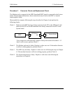
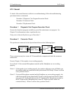
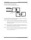
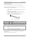
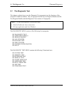
The wireless LAN function wiring diagram is shown below:
v
PJ1
PJ351
SC board
(Switch)
PJ999
System board
PJ100
PJ9
MI board
Antenna Cable
Wireless LAN
board
Left Antenna
Right Antenna
Cable(FL board)
Any of the connections may be disconnected. Disassemble the computer following the steps
described in Chapter 4, perform the following checks:
Check 1 Make sure the connection between the Wireless board, MI board and the System
board (the connector PJ351 on MI board and the System board connector PJ100).
If the connecter is disconnected, connect firmly then return to Procedure 1. If there
is still an error, go to Check 2.
Check 2 Make sure the wireless LAN antennas (black and white) are firmly connected to
the Wireless board. If the antennas are disconnected, connect firmly then return to
Procedure 1. If there is still an error , go to Check 3.
Check 3 Make sure the connection between the SC board PJ999 and the System board PJ9.
If the cable is disconnected, connect firmly then return to Procedure 1. If there is
still an error, perform Procedure 3.
2-48 PORTEGE R100 Maintenance Manual (960-440)