


4 Replacement Procedures 4.17 LCD cable/Wireless LAN cable/Antenna cover
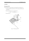
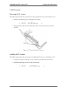
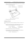
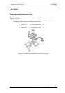
3. Remove the following screws fixing both the hinges of the LCD cover and detach
the LCD cover from the palmrest cover.
• M3×3.5Z BIND screw x2 (on both the sides)
• M2×4Z S-THIN HEAD screw x2 (on both the sides)
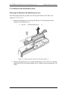
Figure 4-34 Removing the LCD cable
4. Pull out the LCD cable to the LCD cover.
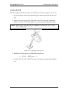
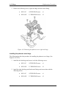
Installing the LCD cable
The following describes the procedure for installing the LCD cable. (See Figures 4-33,
4-34)
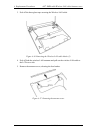
1. Pass the LCD cable from the LCD cover side to palmrest side and secure the
following screws to fix both the hinges of the LCD cover side.
• M3×3.5Z BIND screw x2 (on both the sides)
• M2×4Z S-THIN HEAD screw x2 (on both the sides)
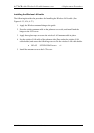
2. Apply the three glass tapes to secure the LCD cable in place.
3. Connect the palmrest side LCD cable (Pass under the LCD cable holder) and
secure the following screw to fix the LCD cable holder.
• M2×3B S-THIN HEAD screw x1
4-44 PORTEGE R100 Maintenance Manual (960-440)