


A DB-15 Applicator Interface Connector provides communication between the print engine and the
associated applicator hardware. In some applications, control signal timing may be a critical element
in the performance of the print engine. Refer to Appendix B for control signal descriptions.
WARNING!! Connecting a data communications cable while the power
is ON may damage the PAX2 print engine.
NOTE: You must supply the interface cables for your application. Refer to
Appendix B for specific cable requirements.
Printer Power
The Power Supply in the PA X 2-Series printer automatically detects the applied line voltage and works
in the 90 to 264 VAC, 48 to 62 Hz range.
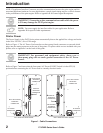
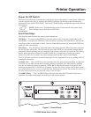
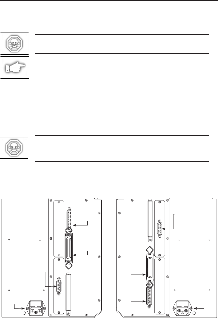
Refer to Figure 1. The AC Power Cord must have a three-prong female connector on one end which
plugs into the mating connector at the rear of the printer. If a power cable was not included with your
printer, refer to Appendix A at the back of this guide.
WARNING!! For personnel and equipment safety, always use a
three-prong plug with an earth ground connection to the AC Power
Source.
Refer to Figure 7 and insure that the front panel AC Power ON/OFF Switch is in the OFF (O)
position before connecting the AC Power cord to a nearby electrical outlet.
2 170PAX2-Series User’s Guide
Introduction
PARALLEL
INTERFACE
CONNECTOR
DB-25 SERIAL
INTERFACE
CONNECTOR
DB-15 APPLICATOR
INTERFACE
CONNECTOR
AC POWER
CONNECTOR
LEFT HAND PAX PRINT ENGINE
RIGHT HAND PAX PRINT ENGINE
PARALLEL
INTERFACE
CONNECTOR
DB-25 SERIAL
INTERFACE
CONNECTOR
AC POWER
CONNECTOR
DB-15 APPLICATOR
INTERFACE
CONNECTOR
Figure 1. Cable Connections