


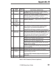

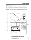


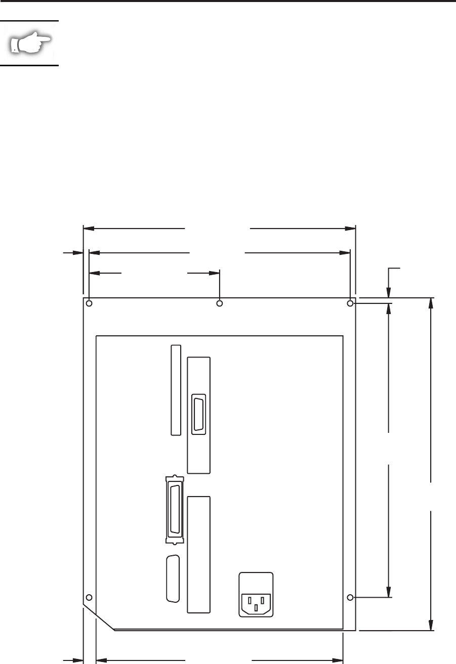
NOTE: Mounting hole locations are identical for both the right hand and
left hand print engines.
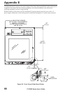
Clearance at the rear panel of the electronics enclosure must provide ample space for electronic
connectors and dressing of the following cables: IEC power cord, serial and/or parallel host
communication cable, optional host communication cable (Coax, Twinax, Ethernet), and the discrete
signal (applicator) interface cable.
The IEC power cord does not have a strain relief on the printer. If the operating characteristics of the
applicator include vibration or strain on the power cord, then the installation shall provide an
appropriate clamping mechanism to avoid unintentional disconnection of the power cord from the
printer.
Appendix E
170PAX2-Series User’s Guide 69
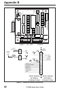
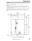
.197"
(5 mm)
.197"
(5 mm)
.451"
(11.45 mm)
8.748"
(222.2 mm)
10.433"
(265 mm)
11.811"
(300 mm)
9.646"
(245 mm)
9.252"
(235 mm)
4.626"
(117.5 mm)
Figure 31. Rear View of Right Hand Printer