


90 34980A User’s Guide
3 Introduction to the Plug-In Modules for the 34980A
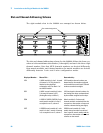
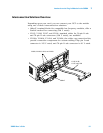
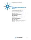
Slot and Channel Addressing Scheme
The eight module slots in the 34980A are arranged as shown below.
The slot and channel addressing scheme for the 34980A follows the form sccc
where s is the mainframe slot number (1 through 8) and ccc is the three-digit
channel number. Note that MUX channels numbers are derived differently
from matrix modules, and channel numbers for matrix modules are derived
differently between 1-wire and 2-wire configuration modes.
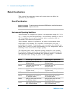
Slot number designations
Displayed Number... Means This... Determined by...
1014 A MUX module is in slot 1, channel
of interest is 14. This channel is
labeled on the simplified
schematics as 014 on Bank 1 of
each MUX module.
MUX module channel numbers are
determined by the numbers assigned
to the switches on each bank. Channel
numbers contain three digits.
3921 A MUX or matrix module is in slot
3, channel of interest is 921
(Analog Bus relay on ABus1)
MUX and matrix channel numbers for
the Analog Bus relays are determined
by the number assigned to the relays.
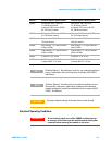
5304 A 34931A, 34932A, 34933A (2-wire
mode) matrix module is in slot 5,
crosspoint is row 3, column 4.
Matrix module (in 2-wire mode)
channel numbers are derived from the
crosspoint or intersection of rows and
columns, columns having two digits).
2437 A 34933A matrix module in 1-wire
mode is in slot 2, matrix of interest
is 4, crosspoint is row 3, column 7.
34933A matrix module (in 1-wire
mode) channel numbers are derived
from a specific matrix number and
the
crosspoint or intersection of rows and
columns on that matrix.