


Low Frequency Multiplexer Switch Modules 4
34980A User’s Guide 109
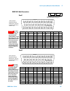
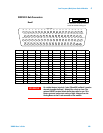
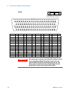
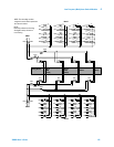
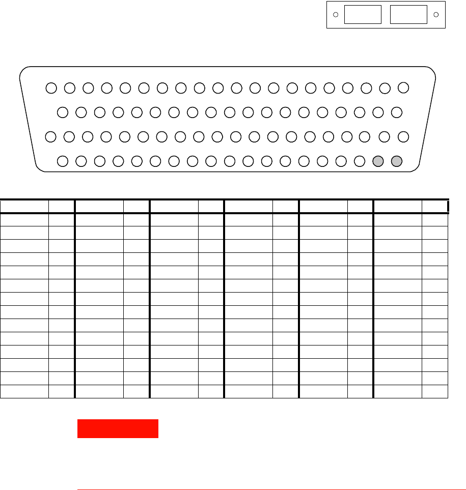
34922A D-Sub Connectors
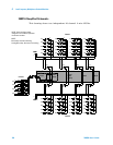
Bank 1
For orientation, the D-sub connector
end of the module is facing you.
Bank 2
Bank 1
10H6H 6L 1H 1L 7H 7L
COM
1L 3H 3L 9H 9L 4H 4L
COM
1H2H 2L 10L 5L5H
12 3 4 5 6 7 891011121314151617
18 19
20
12H16H 16L 11H 11L 17H 17L 12L 8H 8L 34H 34L 19H 19L 14H 14L 20H 20L Interlock1
21
22 23
24 25
26
27
28 29
30 31
32 33 34 35
36
37
38 39
GND 26H 26L 21H 21L 22H 22L 27H 27L 13H 13L 28H 28L 24H 24L 29H 29L 15H 15L Interlock 1
40
41
42 43
44
45 46
47
48
49 50 51
52
53 54 55
56
57 5958
60
61 62
63 64
65
66
67 68
69 70
71 72 73 74
75
76
77 78
GND 32H 32L 31H 31L 33H 33L 18H 18L 23H 23L 35H 35L 30H 30L 25H 25L
NC NC
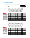
Description Pin Description Pin Description Pin Description Pin Description Pin Description Pin
1H 3 8H 29 15H 57 22H 45 29H 55 COM1 H 9
1L 4 8L 30 15L 58 22L 46 29L 56 COM1 L 10
2H 7 9H 13 16H 21 23H 69 30H 73 Interlock 1 39
2L 8 9L 14 16L 22 23L 70 30L 74 Interlock 1 59
3H 11 10H 17 17H 25 24H 53 31H 63 GND 40
3L 12 10L 18 17L 26 24L 54 31L 64 GND 60
4H 15 11H 23 18H 67 25H 75 32H 61 No Connect 77
4L 16 11L 24 18L 68 25L 76 32L 62 No Connect 78
5H 19 12H 27 19H 33 26H 41 33H 65
5L 20 12L 28 19L 34 26L 42 33L 66
6H 1 13H 49 20H 37 27H 47 34H 31
6L 2 13L 50 20L 38 27L 48 34L 32
7H 5 14H 35 21H 43 28H 51 35H 71
7L 6 14L 36 21L 44 28L 52 35L 72
WARNING
As a safety feature, interlock 1 pins (39 and 59) on Bank 1 must be
shorted to enable the Bank 1 Analog Bus relays to close. The
optional 34922T terminal block shorts these pins for you. This
feature protects inadvertent routing of high voltages from the
Analog Buses to the D-sub connector of the module.